
A clamping device and sputtering equipment used in sputtering equipment

A clamping device and sputtering technology, which is applied in the field of sputtering coating equipment, can solve the problems of warping and deformation of the mask plate, shadowing of the substrate film formation, and pollution of the sputtering chamber due to film layer falling off, so as to avoid improper lamination Tight, avoid film shadow, avoid warping and deformation effect

Active Publication Date: 2021-06-01
SHENZHEN CHINA STAR OPTOELECTRONICS SEMICON DISPLAY TECH CO LTD
View PDF20 Cites 0 Cited by
  • Summary
  • Abstract
  • Description
  • Claims
  • Application Information

AI Technical Summary

Problems solved by technology

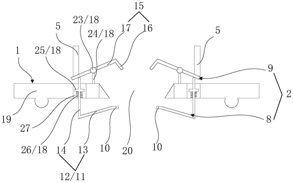
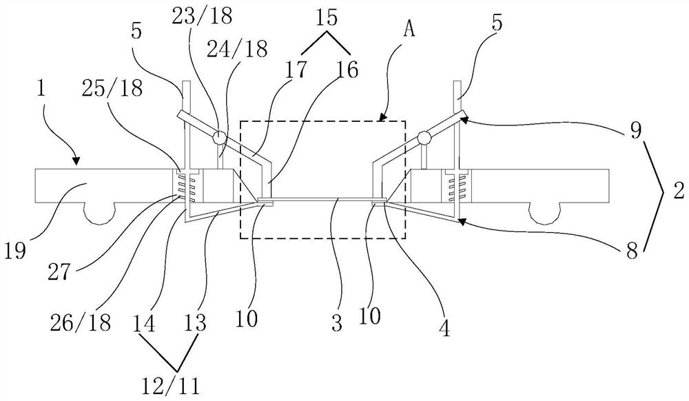
[0004] The embodiment of the present application provides a clamping device and sputtering equipment used in sputtering equipment to solve the warping and deformation of the mask during the substrate sputtering film formation process, and the sputtered film layer on the mask falls off and pollutes the sputtering. The problem of shadows in the plating chamber and substrate film formation

Method used


Image

  • A clamping device and sputtering equipment used in sputtering equipment
  • A clamping device and sputtering equipment used in sputtering equipment
  • A clamping device and sputtering equipment used in sputtering equipment

Examples


Embodiment Construction

[0030] Specific structural and functional details disclosed herein are representative only and are for purposes of describing example embodiments of the present application. This application may, however, be embodied in many alternative forms and should not be construed as limited to only the embodiments set forth herein.

[0031] In the description of this application, it should be understood that the terms "central", "lateral", "upper", "lower", "left", "right", "vertical", "horizontal", "top", The orientation or positional relationship indicated by "bottom", "inner" and "outer" are based on the orientation or positional relationship shown in the drawings, and are only for the convenience of describing the application and simplifying the description, rather than indicating or implying the referred device Or elements must have a certain orientation, be constructed and operate in a certain orientation, and thus should not be construed as limiting the application. In addition,...


PUM


Abstract

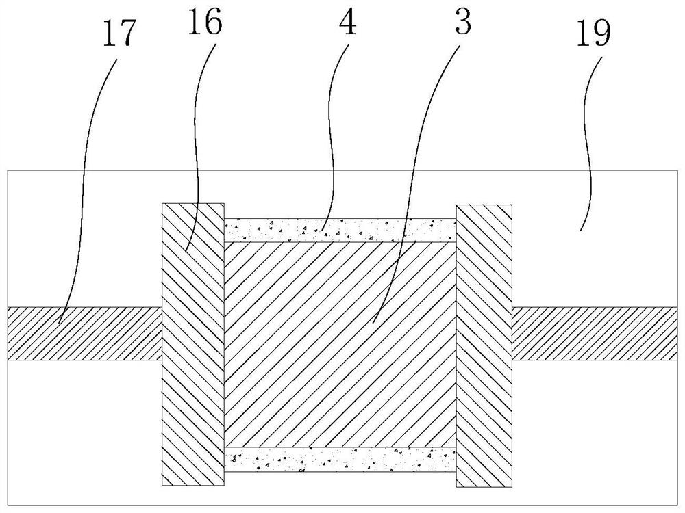
The present application discloses a clamping device used in sputtering equipment and sputtering equipment. The clamping device includes: a clamp for clamping a substrate and a mask correspondingly; a driving device connected with the clamp for driving The clamp is clamped or loosened; wherein, an opening matching the shape and size of the opening of the mask is provided on the clamp, so that after the clamp clamps the mask and the substrate, the side of the clamp close to the mask is on the substrate The orthographic projection on the mask completely covers the orthographic projection of the mask on the substrate, and the opening of the fixture is in alignment with the opening of the mask, exposing the sputtering area of ​​the substrate for the sputtering equipment to perform sputtering on the sputtering area of ​​the substrate. Sputtering. This application can prevent the mask plate from being covered by the sputtered film layer during the sputtering film formation process of the substrate, thereby avoiding the warping deformation of the mask plate, falling off of the sputtered film layer on the mask plate and polluting the sputtering chamber and There is a shadow problem in substrate film formation.

Description

technical field [0001] The present application relates to the technical field of sputtering coating equipment, in particular to a clamping device and sputtering equipment used in sputtering equipment. Background technique [0002] Sputtering coating machines are widely used in the coating process of TP (Touch Panel, touch screen), LCD (Liquid Crystal Display, liquid crystal display), OLED (Organic Light-Emitting Diode, organic light-emitting diode), and the substrate is required for sputtering coating The carrier device, the substrate carrier device is equipped with a substrate fixing device; there are many film forming processes that do not require the entire substrate to be filmed, but need to deposit a film of a specific shape, which requires the use of metal masks and sputtering coatings. Its supporting tight alignment system must ensure that the relative position between the metal mask and the substrate remains unchanged during the film forming process in order to produ...

Claims


Application Information

Patent Timeline
Patent Type & Authority Patents(China)
IPC IPC(8): C23C14/04C23C14/35
CPCC23C14/042C23C14/35
Inventor 谭伟李金川
Owner SHENZHEN CHINA STAR OPTOELECTRONICS SEMICON DISPLAY TECH CO LTD
Learn More