A plugging device and plugging method for oil and gas pipeline reverse well drilling deviated wells
A technology for plugging devices and oil and gas pipelines, applied in safety devices, sealing/isolation, wellbore/well components, etc., can solve the problems of plugging devices such as heavy, heavy, and poor economy, and improve the effectiveness of plugging , The effect of facilitating construction
- Summary
- Abstract
- Description
- Claims
- Application Information
AI Technical Summary
Problems solved by technology
Method used
Image

Examples
Embodiment 1
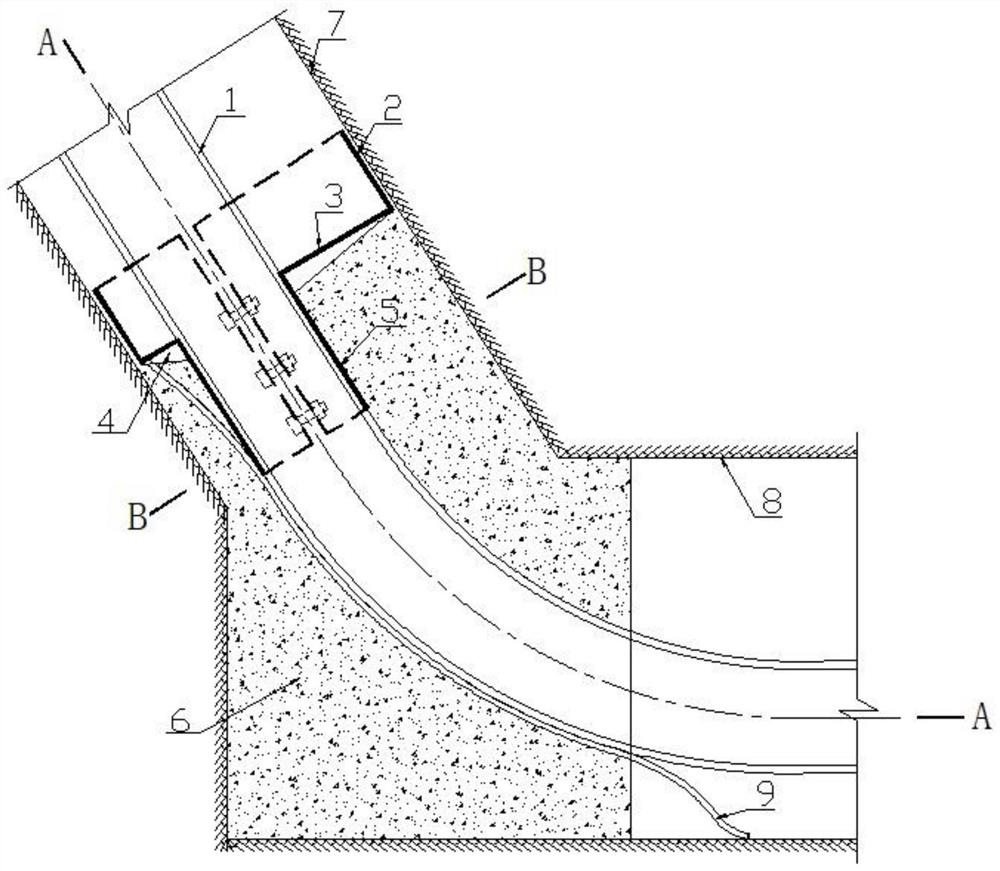
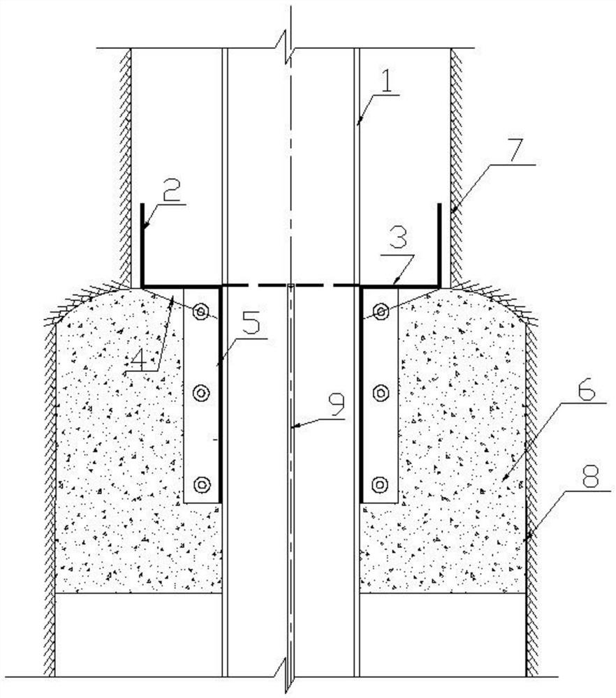
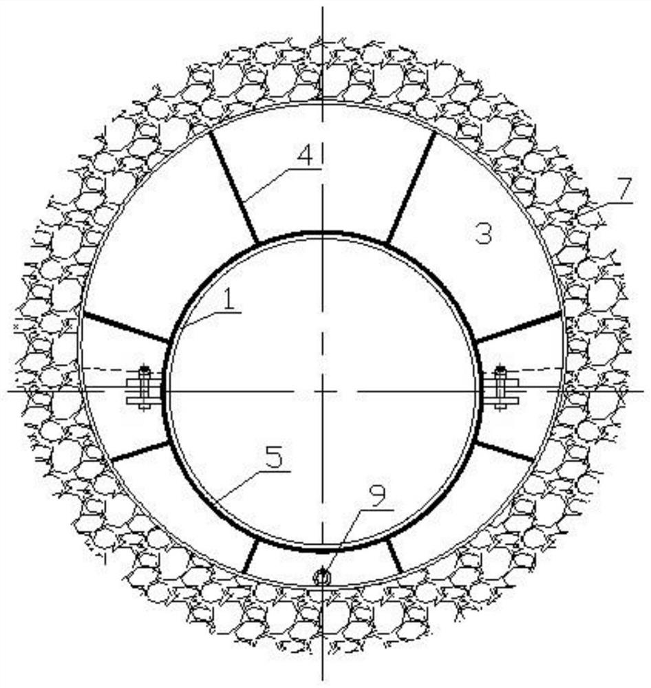
[0031] Such as Figure 1-3 As shown, what is described in Embodiment 1 of the present invention is a device for oil and gas pipeline back-drilling deviated well plugging, the device includes:
[0032] Tray 3, which is an inverted convex shape, includes a connected upper half cylinder 2 and a lower half cylinder 5, the tray 3 is two symmetrical pieces and is sleeved on the pipeline 1 through a detachable connector;
[0033] The stiffening plate 4 is arranged between the outer bottom end of the upper semi-cylinder 2 and the outer side of the lower semi-cylinder 5, and there are multiple stiffening plates 4;
[0034] A permanent support structure 6, which is arranged between the tray 3 and the tunnel rock wall 8, and the permanent support structure 6 is located below the upper half cylinder 2;
[0035] Drainage pipe 9, its inlet end is connected with the bottom of upper semi-cylinder 2, and the outlet end of drainpipe 9 is connected with drainage ditch in the tunnel.
[0036] T...
Embodiment 2
[0046] Embodiment 2 of the present invention describes a method for plugging deviated wells of oil and gas pipelines, the method comprising:
[0047] Step 1. Set the tray 3 on the outside of the pipeline 1 so that the tray 3 hugs the pipeline 1 tightly, and then fix the tray 3 with bolt connectors;
[0048] Step 2. Insert the drainage pipe 9 into the reserved hole at the bottom of the upper semi-cylinder 2 to transport the crack water in the inclined shaft to the drainage ditch in the tunnel;
[0049] Step 3, sealing the space between the outer side of the tray 3 and the raise drilling wall 7 tightly with a filler;
[0050]Step 4, pouring concrete between the tray 3 and the tunnel rock wall 8 to form a permanent support structure.
[0051] Further, in step 1, the tray 3 is fixed by bolts on the lower semi-cylinder 5 and reinforced by a plurality of stiffening plates 4 in the circumferential direction.
PUM
 Abstract
Description
Claims
Application Information
 - R&D
- Intellectual Property
- Life Sciences
- Materials
- Tech Scout
- Unparalleled Data Quality
- Higher Quality Content
- 60% Fewer Hallucinations
Browse by: Latest US Patents, China's latest patents, Technical Efficacy Thesaurus, Application Domain, Technology Topic, Popular Technical Reports.
© 2025 PatSnap. All rights reserved.Legal|Privacy policy|Modern Slavery Act Transparency Statement|Sitemap|About US| Contact US: help@patsnap.com