
Wind power generator unit heat-dissipating device and method based on separate heat pipe heat exchanger

A separate heat pipe and wind turbine technology, applied in indirect heat exchangers, lighting and heating equipment, etc., can solve the problems of local heat accumulation, poor airflow organization, dust accumulation in the engine room, etc., and achieve small structural changes and prevent liquid medium from backflow. , the effect of no heat exchange dead angle

Pending Publication Date: 2019-08-27
CHINA HUANENG GRP CO LTD +1
View PDF0 Cites 0 Cited by
  • Summary
  • Abstract
  • Description
  • Claims
  • Application Information

AI Technical Summary

Problems solved by technology

One is passive heat dissipation, that is, an air inlet hole is set at the front center of the bottom of the cabin, and an air outlet hole is set at the rear center of the cabin, and the natural flow is used to form air flow in the cabin to achieve the purpose of heat dissipation, but this method The disadvantages are poor organization of airflow, local heat accumulation, and severe dust accumulation in the cabin.
The second method is to circulate the cooling oil from the casing of gear boxes and other equipment to the outside of the engine room, and then use the air cooling equipment outside the engine room to cool it, and return it to the equipment casing. The disadvantage of this method is that the process is complicated and the energy consumption is high.

Method used


Image

  • Wind power generator unit heat-dissipating device and method based on separate heat pipe heat exchanger
  • Wind power generator unit heat-dissipating device and method based on separate heat pipe heat exchanger
  • Wind power generator unit heat-dissipating device and method based on separate heat pipe heat exchanger

Examples


Embodiment Construction

[0032] The present invention will be described in further detail below in conjunction with accompanying drawing and specific embodiment, and its content is explanation of the present invention rather than limitation:

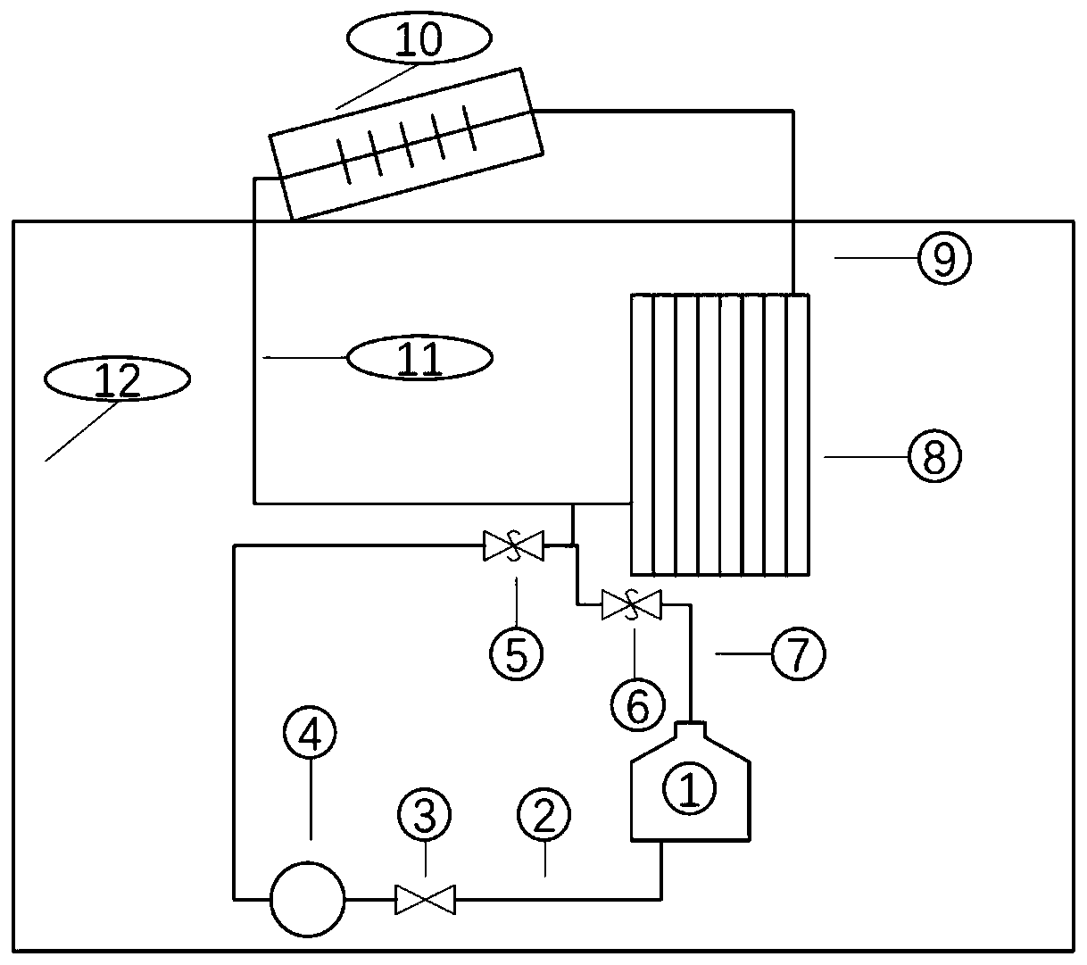
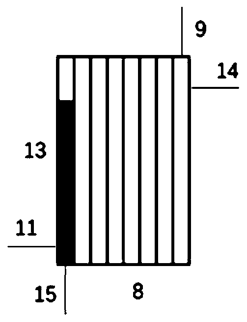
[0033] figure 1 It is a schematic diagram of the overall structure of the wind turbine cooling device based on the separated heat pipe heat exchanger of the present invention, including a medium storage device 1, a medium delivery pipe 2, a liquid inlet one-way valve 3, a pump 4, a liquid return one-way valve 6, a medium Return pipe 7, heat pipe evaporating section 8, steam rising pipe 9, heat pipe condensing section 10 and liquid downpipe 11;

[0034] The steam outlet of the heat pipe evaporating section 8 is connected with the vapor inlet of the heat pipe condensing section 10 through the steam riser 9, the liquid outlet of the heat pipe condensing section 10 is connected with the liquid inlet of the heat pipe evaporating section 8 through a liquid downcomer 1...


PUM

PropertyMeasurementUnit
Angleaaaaaaaaaa

Abstract

The invention discloses a wind power generator unit heat-dissipating device and a wind power generator unit heat-dissipating method based on a separate heat pipe heat exchanger, and belongs to the technical field of wind power generator unit temperature control. The internal part of a cabin of the wind power generator unit is subjected to heat dissipation by the separate heat pipe heat exchanger and the internal structure of the original cabin is changed little, so that manufacturing and mounting are facilitated; and a heat pipe condensation section and a heat pipe evaporation section of the separate heat pipe heat exchanger can be arranged separately, the heat pipe evaporation section is arranged on a part, needing heat dissipation, in the cabin, the heat pipe condensation section is arranged at the top of the cabin, a medium in the heat pipe evaporation section is changed into a gaseous medium after absorbing heat, the gaseous medium flows to the heat pipe condensation section at thetop of the cabin through a vapor ascending pipe and exchanges heat with the external air to be condensed into a liquid medium, the liquid medium returns to the heat pipe evaporation section under thegravity action and through a liquid descending pipe, and continuous transfer of heat is completed by depending on continuous phase change of the interal medium. The wind power generator unit heat-dissipating device has high heat-dissipating efficiency, can effectively solve the heat dissipation problem of a rotating part and an electric appliance component in the cabin and has extremely high practical value.

Description

technical field [0001] The invention belongs to the technical field of temperature control of a wind power generating set, and in particular relates to a cooling device and method for a wind generating set based on a separate heat pipe heat exchanger. Background technique [0002] During the actual operation of the wind turbine, some rotating parts and electrical components will generate a lot of heat. If the heat cannot be conducted in time, it will cause thermoplastic defects and fractures in the rotating parts, causing failure. At the same time, Excessive heat accumulation will also lead to aging of electrical components, deterioration of insulation performance, and even cause fires in severe cases. In my country's three northern regions, the summer is hot and dry, and the external temperature is relatively high, reaching about 40 degrees Celsius, while the internal temperature in the cabin is as high as 60 degrees Celsius or more due to the heat production of the gearbox...

Claims


Application Information

Patent Timeline
IPC IPC(8): F28D15/02F28D15/06
CPCF28D15/0266F28D15/06
Inventor 郭雨桐陈新明刘鑫闫姝史绍平
Owner CHINA HUANENG GRP CO LTD
Learn More