
Novel road bridge beam supporting seat dustproof structure

A technology for highway bridges and dust-proof structures, applied in bridges, bridge parts, bridge construction, etc., can solve the problems of exposed surface, inconvenient maintenance, inconvenient inspection, etc., to achieve good durability, improve inspection efficiency, and long-term benefits.

Pending Publication Date: 2019-08-30
江苏京沪高速公路有限公司
View PDF0 Cites 0 Cited by
  • Summary
  • Abstract
  • Description
  • Claims
  • Application Information

AI Technical Summary

Problems solved by technology

5201 silicone grease can play a good lubricating effect, but 5201 silicone grease is very easy to absorb dust and various solid particles in the air, because the PTFE sheet will normally slide out of the upper steel plate within a certain range ( Generally a few centimeters), causing the surface to be exposed, causing dust and various solid particles in the air to enter between the stainless steel plate and the PTFE sheet, which will significantly increase the friction between the two and speed up the sliding of the slide-type rubber bearing. The speed at which the top PTFE sheet is worn away
The existing rubber strip adopts non-enclosed shielding, and the rubber strip is only simply enclosed around the support, which is not easy to intercept the water seepage of the bridge deck at the expansion joint, causing corrosion of the steel backing plate of the bridge support and other accessories;
[0007] (3) Inconvenient inspection
Existing bearing dust covers are not easy to check the specific conditions of the bearings when inspecting the bridge bearings. Objects such as sticks need to be used to lift the rubber strips to check the bearing conditions, and this action itself will also cause damage to the dust cover ;
[0008] (4) Inconvenient maintenance

Method used


Image

  • Novel road bridge beam supporting seat dustproof structure
  • Novel road bridge beam supporting seat dustproof structure

Examples


Embodiment Construction

[0029] In the description of the present invention, it is necessary to understand that the orientations or positional relationships indicated by "upper", "lower", "top", "bottom", "inner" and "outer" are all based on what is shown in the accompanying drawings. Orientation or positional relationship, the purpose is only to facilitate the description of the present invention and simplify the description, and does not indicate or imply that the referred components must have a specific orientation, be constructed and operated in a specific orientation, and therefore cannot be construed as limiting the present invention.

[0030] Specific embodiments of the present invention will be described in detail below in conjunction with the accompanying drawings.

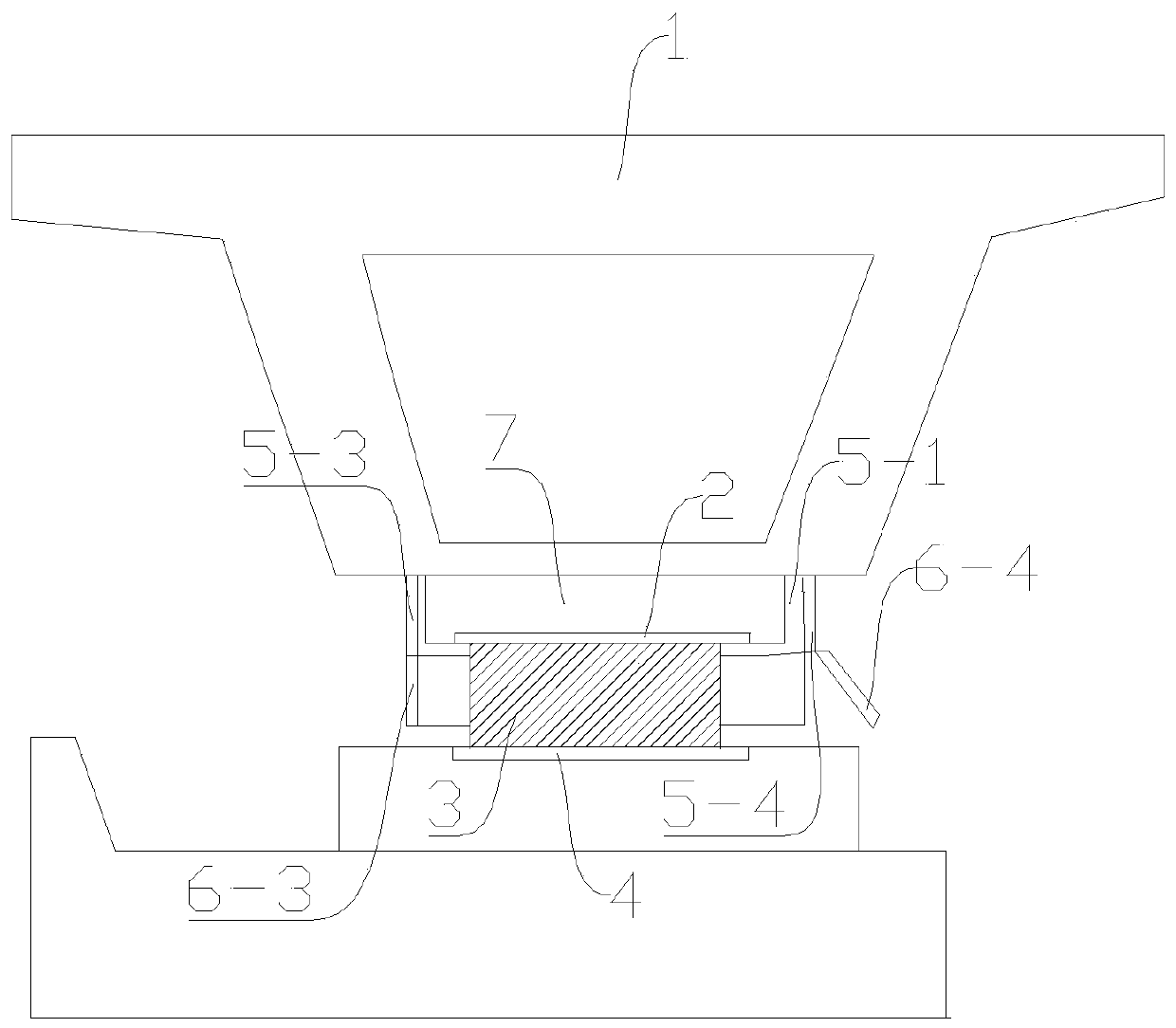
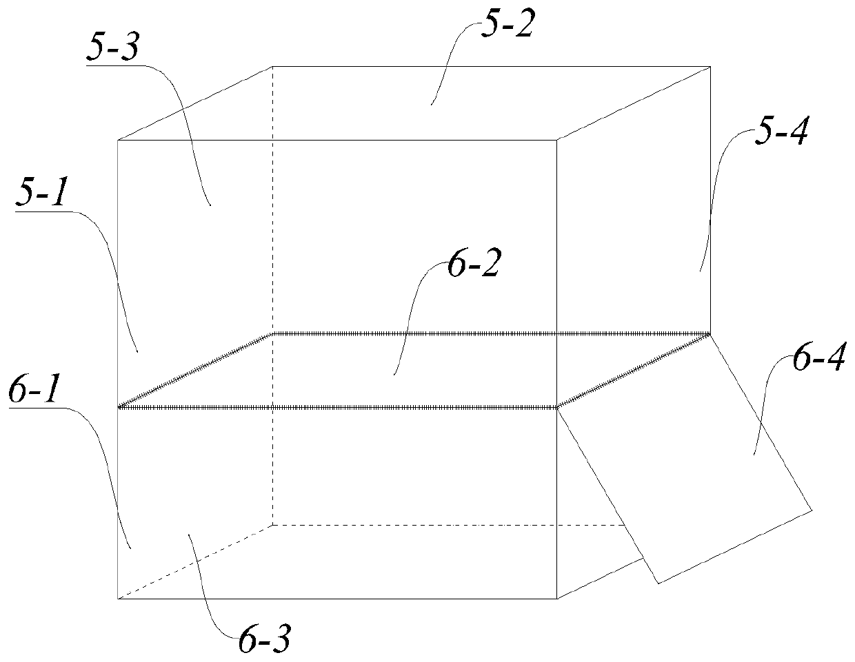
[0031] A new type of dust-proof structure for highway bridge bearings, such as Figure 1-2 As shown, it includes a beam body 1, an upper pad stone 7 located under the beam body 1, an upper steel plate 2 located under the upper pa...


PUM


Abstract

The invention discloses a novel road bridge beam supporting seat dustproof structure, including a beam body, an upper cushion stone and an upper steel plate located below the beam body, a supporting seat located below the upper steel plate, a fixed side plate enclosing the upper cushion stone and the upper steel plate, a movable side plate located below the fixed side plate and enclosing the supporting seat, and a lower steel plate located below the supporting seat, and the upper edge of the movable side plate is hinged to the lower edge of the fixed side plate. According to the novel road bridge beam supporting seat dustproof structure, manufacture of the fixed side plate and the movable side plate by perspex is adopted, durability is good, and the structure is not prone to aging; and corrosion of the steel plate of the bridge beam supporting seat caused by seepage of water is prevented effectively, the influence of dust on a sliding surface of the supporting seat is prevented, agingof the supporting seat is slowed, and the life of the supporting seat is prolonged. The state of the supporting seat is tested visually without the need of using other methods, testing efficiency is improved, a supporting seat maintenance operation is not hindered, a replacement operation of the supporting seat during later maintenance is convenient, and long-time benefits are obvious.

Description

technical field [0001] The invention relates to the technical field of protection devices for highway bridge supports, in particular to a novel highway bridge support dustproof structure. Background technique [0002] The bridge bearing is an important part of the bridge structure. It is an important connecting part of the bridge superstructure (beam body) and substructure (pier column). It is also necessary to adapt to the horizontal displacement of the superstructure caused by live loads and temperature changes and the fulcrum rotation angle displacement caused by deflection. [0003] When the new road bridge is completed, or the old road bridge is replaced with a support, under the expansion joint, the pad stone steel plate on the bottom surface of the main girder is pressed against the polytetrafluoroethylene sheet on the top of the slide rubber support, and their sliding The coefficient of friction is between 0.04-0.08. In engineering practice, if a layer of transluce...

Claims


Application Information

Patent Timeline
IPC IPC(8): E01D19/04
CPCE01D19/04
Inventor 高兆东张兴明邱林泽
Owner 江苏京沪高速公路有限公司
Learn More