
Method and equipment enabling air compressor to achieve constant-pressure air supply

A technology of air compressors and equipment, which is applied in the direction of mechanical equipment, machines/engines, liquid variable capacity machinery, etc. It can solve the problems of large fluctuations in air supply pressure, not constant, and inability to adjust the air supply volume.

Active Publication Date: 2019-08-30
SANHE ELECTRIC FUJIAN
View PDF8 Cites 2 Cited by
  • Summary
  • Abstract
  • Description
  • Claims
  • Application Information

AI Technical Summary

Problems solved by technology

[0003] Since the existing air compressor starts the motor to drive the compressor when the pressure of the air storage tank drops to a certain value such as 0.3--0.4MPa, and automatically stops when the exhaust pressure reaches the rated pressure such as 0.7MPa, the existing air compressor The pressure of the air storage tank of the machine is always changing, not constant, so the air supply cannot be adjusted according to the change of the load air consumption
[0004] In addition, the existing air compressor adopts the on / off control method of the intake valve. When the pressure reaches the upper limit, the valve closes, and the compressor enters light-load operation. When the pressure reaches the lower limit, the valve opens, and the compressor enters full-load operation. The frequent light-load and full-load operation of the air compressor, and the frequent start and stop of the motor make the air supply pressure fluctuate greatly, which is not conducive to the user's use
At the same time, the frequent start and stop of the air compressor will cause serious heating of the motor windings and affect the service life of the motor

Method used


Image

  • Method and equipment enabling air compressor to achieve constant-pressure air supply
  • Method and equipment enabling air compressor to achieve constant-pressure air supply
  • Method and equipment enabling air compressor to achieve constant-pressure air supply

Examples


Embodiment Construction

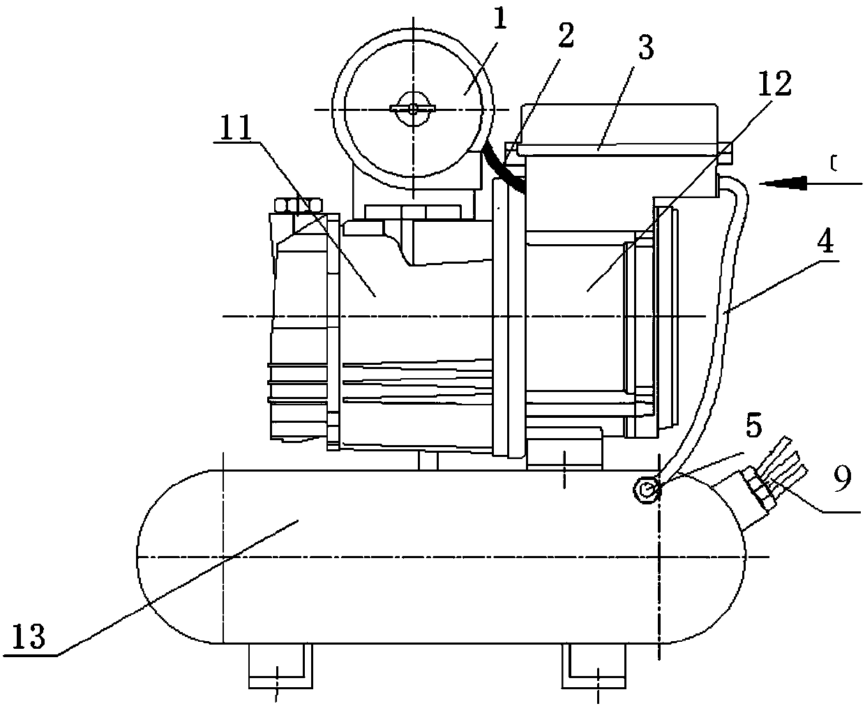
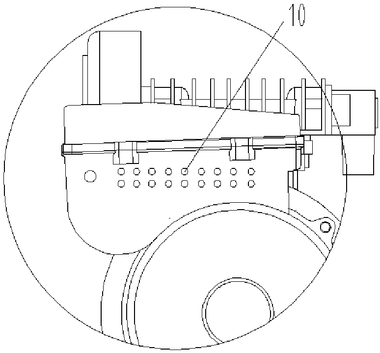
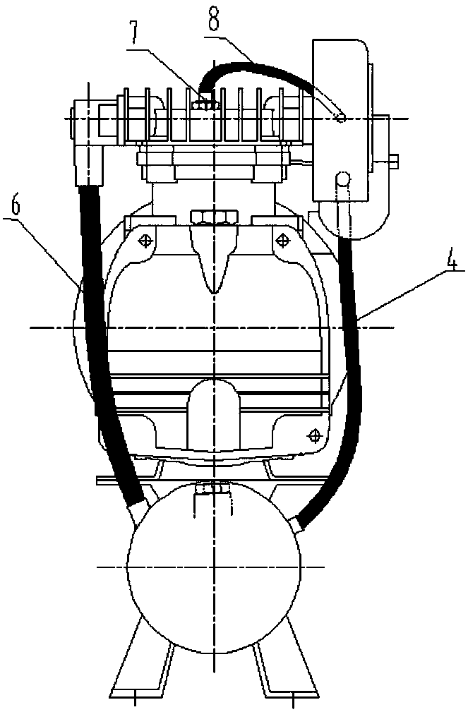
[0041] see Figure 1-Figure 7 , a method of the present invention to enable the air compressor to achieve constant pressure gas supply, comprising: the air compressor 11 compresses and outputs gas; the gas storage tank 13 connected to the output end of the air compressor 11 receives the gas compressed by the air compressor and Supply gas to the user; the pressure sensor 5 connected to the gas storage tank 13 detects the air supply pressure in the gas storage tank 13, and outputs a pressure detection signal; the controller connected to the pressure sensor 5 according to the rated air pressure value P0 and The difference of the pressure P1 of the pressure detection signal output by the pressure sensor 13 generates a motor control signal; the variable frequency motor 12 connected between the controller and the air compressor 11 controls its driving air pressure according to the motor control signal output by the controller. The working speed of the air compressor, so that the air...


PUM


Abstract

The invention discloses method and equipment enabling an air compressor to achieve constant-pressure air supply. The method comprises the steps that the air compressor compresses and conveys out air;an air storage tank at the output end of the air compressor is connected to receive air compressed by the air compressor, and air is supplied to a user; a pressure sensor of the air storage tank is connected to detect air supply pressure in the air storage tank, and a pressure detection signal is output; a controller of the pressure sensor is connected, and a motor control signal is generated according to the difference value of a rated air pressure value P0 and pressure P1 of the pressure detection signal output by the pressure sensor; and a variable frequency motor connected between the controller and the air compressor controls rotation speed for driving the air compressor to work according to the motor control signal output by the controller, and thus the air compressor provides constant-pressure air for the user.

Description

technical field [0001] The invention relates to the technical field of air compressors, in particular to a method and equipment for enabling an air compressor to realize constant-pressure air supply. Background technique [0002] The air compressor is a kind of equipment used to compress gas. It is directly driven by the motor to make the crankshaft rotate, and the connecting rod is driven to make the piston reciprocate, causing the volume of the cylinder to change. Due to the change of the pressure in the cylinder, the air enters the cylinder through the air filter (muffler) through the intake valve. The directional valve (check valve) enters the air storage tank, and when the exhaust pressure reaches the rated pressure such as 0.7MPa, it is controlled by the pressure switch and automatically shuts down. When the pressure of the gas storage tank drops to a certain value such as 0.3--0.4MPa, the pressure switch is automatically connected and started. [0003] Since the exi...

Claims


Application Information

Patent Timeline
Patent Type & Authority Applications(China)
IPC IPC(8): F04B49/06F04B49/08F04B39/06
CPCF04B39/06F04B49/06F04B49/08
Inventor 施秋铃
Owner SANHE ELECTRIC FUJIAN
Learn More