
Pneumatic shield gate gas path switching device

A pneumatic shield and switching device technology, applied in the direction of valve devices, valve operation/release devices, engine components, etc., can solve problems such as difficult to achieve precise, complex and multi-functional control objectives, and achieve convenient hoisting and rich control Function, convenient and flexible control effect

Active Publication Date: 2019-08-30
湖南江河能源科技股份有限公司
View PDF8 Cites 1 Cited by
  • Summary
  • Abstract
  • Description
  • Claims
  • Application Information

AI Technical Summary

Problems solved by technology

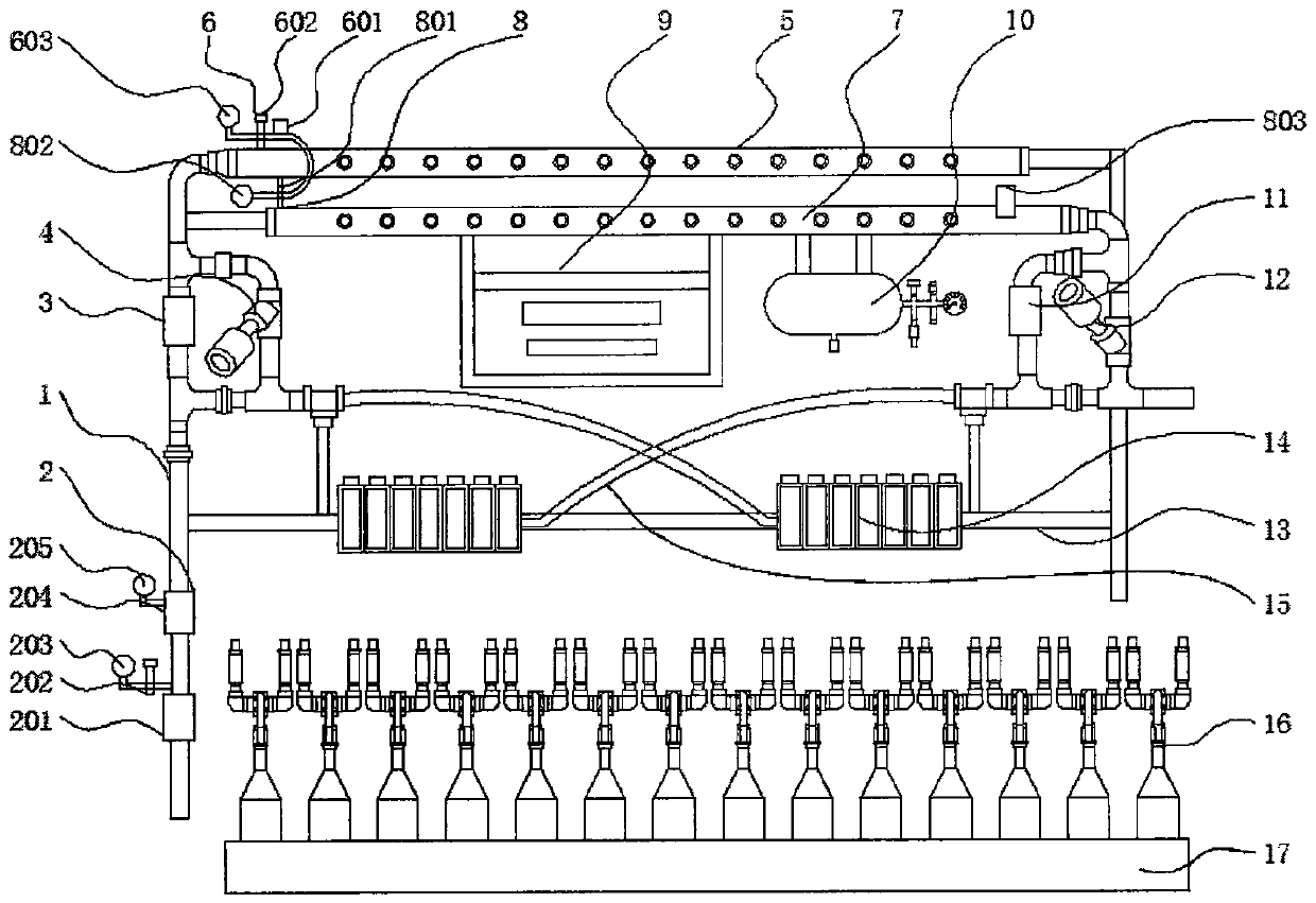
[0004] The object of the present invention is to provide a pneumatic shield gate gas circuit switching device to solve the gas circuit switching device of the existing pneumatic gate proposed in the above background technology. The structure is relatively simple, and a single pipeline is usually used for unified air bag Inflating and exhausting operations, the control part only has a few solenoid valves (such as the main inflation valve and the main exhaust valve), it is difficult to achieve precise, complex and multi-functional control goals, and manual operation is only for the overall inflation and exhaustion of the gate. Exhaust, it is impossible to artificially correct the large deviation of a certain gate

Method used


Image

  • Pneumatic shield gate gas path switching device
  • Pneumatic shield gate gas path switching device
  • Pneumatic shield gate gas path switching device

Examples


Embodiment Construction

[0023] The following will clearly and completely describe the technical solutions in the embodiments of the present invention with reference to the accompanying drawings in the embodiments of the present invention. Obviously, the described embodiments are only some, not all, embodiments of the present invention. Based on the embodiments of the present invention, all other embodiments obtained by persons of ordinary skill in the art without making creative efforts belong to the protection scope of the present invention.

[0024] In the description of the present invention, unless otherwise stated, the meaning of "plurality" is two or more; the terms "upper", "lower", "left", "right", "inner", "outer" , "front end", "rear end", "head", "tail", etc. indicate the orientation or positional relationship based on the orientation or positional relationship shown in the drawings, and are only for the convenience of describing the present invention and simplifying the description, rather...


PUM


Abstract

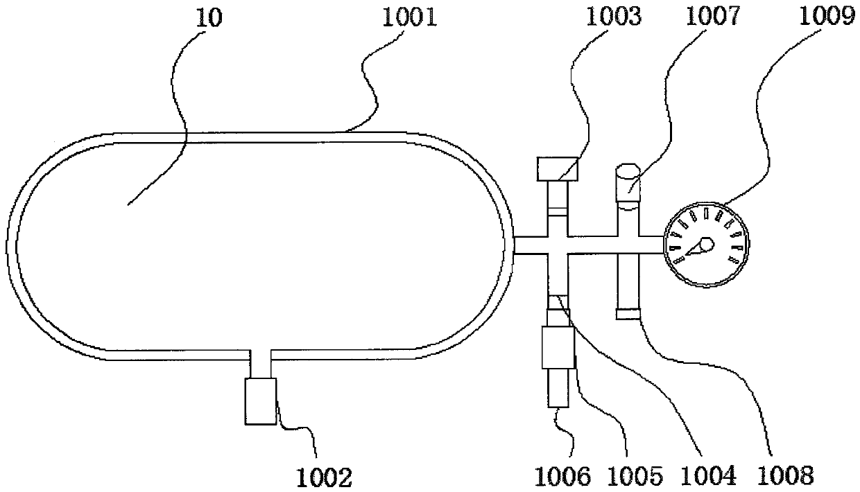
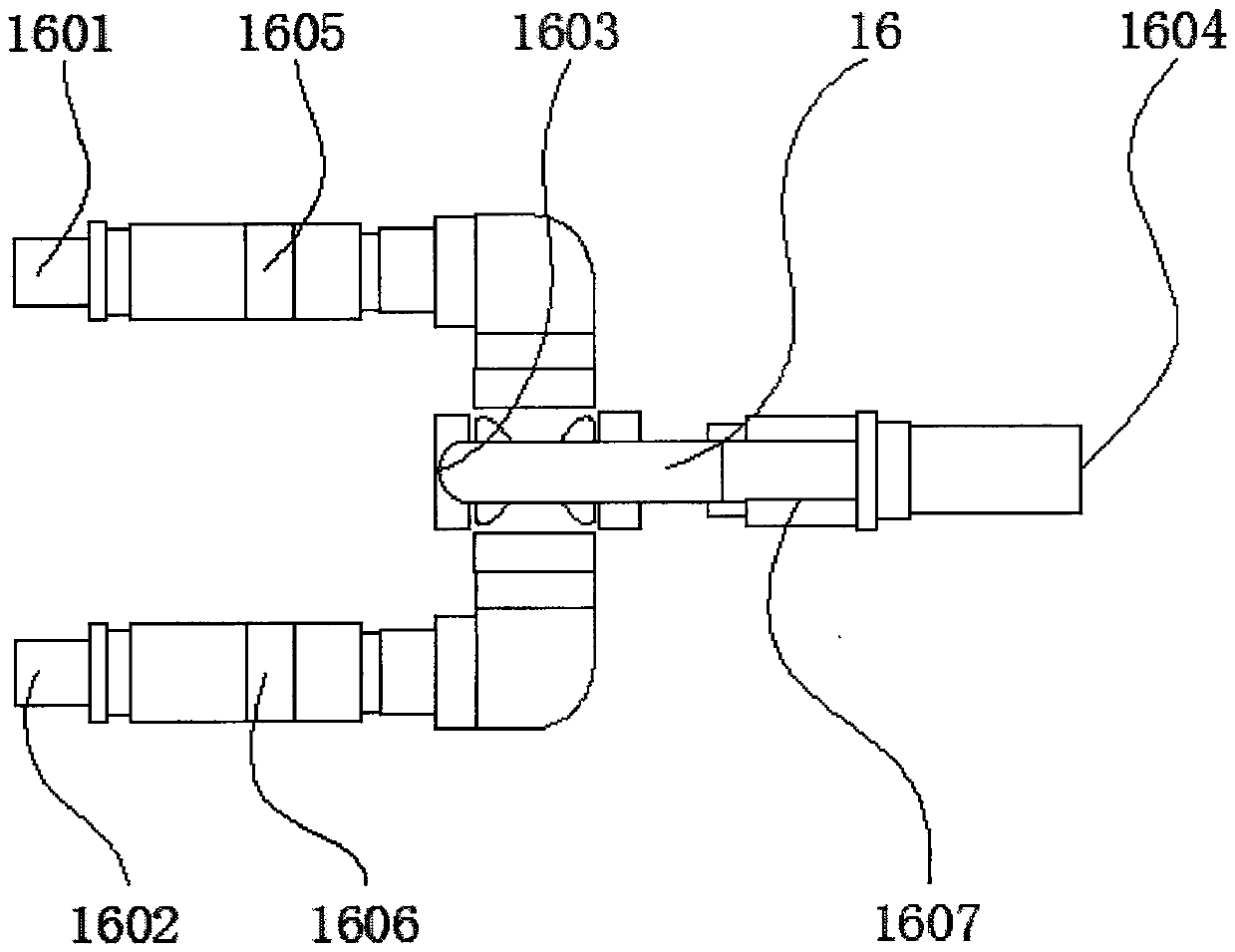
The invention discloses a pneumatic shield gate gas path switching device, and relates to the technical field of pneumatic shield gates. The pneumatic shield gate gas path switching device comprises an air inlet pipeline, an inflation pipeline, an exhaust pipeline and a rack, wherein an air inlet valve assembly is installed on one side below the air inlet pipeline; the inflation pipeline is installed above the top end of the air inlet pipeline; the inflation valve assembly is installed on the left side of the inflation pipeline; the exhaust pipeline is installed below the inflation pipeline; an exhaust valve assembly is arranged on the left side of the exhaust pipeline; a main adjusting inflation manual ball valve is arranged below one side, close to the air inlet pipeline, of the inflation pipeline; and a main adjusting inflation sliding valve is arranged on one side of the main adjusting inflation manual ball valve. The pneumatic shield gate gas path switching device has the beneficial effects that by arranging double-loop switching, the device can meet the fast and high-precision control requirements on a gate; by arranging manual automatic switching, the control function of thegate is enriched, and the safety and the reliability are higher; and by being provided with various types of air valves, the safety of system hardware is improved.

Description

technical field [0001] The invention relates to the technical field of pneumatic shield gates, in particular to a gas circuit switching device for pneumatic shield gates. Background technique [0002] Pneumatic shield gate refers to the use of compressed air as the power source to control the fluctuation of the gate by inflating and exhausting the air bag supporting the steel shield gate. Pneumatic gates are not only safe and environmentally friendly, but also have lower overall manufacturing costs and longer service life. In the process of using the pneumatic shield gate, the corresponding gate air circuit switching device is required. The gas circuit switching device is generally composed of various functional gas valves (such as ball valves, pressure regulating valves, slide valves, safety relief valves, one-way valves, etc.) and solenoid valves. electrical control system. [0003] The gas circuit switching device of the existing pneumatic brake has a relatively simple...

Claims


Application Information

Patent Timeline
Patent Type & Authority Applications(China)
IPC IPC(8): F16K11/10F16K31/12
CPCF16K11/10F16K31/12
Inventor 周威秦新风秦永燕
Owner 湖南江河能源科技股份有限公司
Learn More