Waste gas treatment catalytic device

A catalytic device and waste gas treatment technology, applied in incinerators, using liquid separation agents, chemical instruments and methods, etc., can solve the problems of increasing impurities and affecting the adsorption and precipitation of impurities.

Active Publication Date: 2019-08-30
南京金帝华阳环境检测有限公司
View PDF10 Cites 0 Cited by
  • Summary
  • Abstract
  • Description
  • Claims
  • Application Information

AI Technical Summary

Problems solved by technology

[0005] The above-mentioned equipment pre-filters the impurities and dust in the exhaust gas, so that the impurities and dust fall into the water-soluble tank, but after long-term use, the impurities in the water-soluble tank will increase, which will affect the adsorption of impurities in the exhaust gas by the solvent in the water-soluble tank and the absorption of impurities. precipitation

Method used


Image

  • Waste gas treatment catalytic device
  • Waste gas treatment catalytic device
  • Waste gas treatment catalytic device

Examples


Embodiment Construction

[0031] The present invention will be described in further detail below in conjunction with the accompanying drawings.

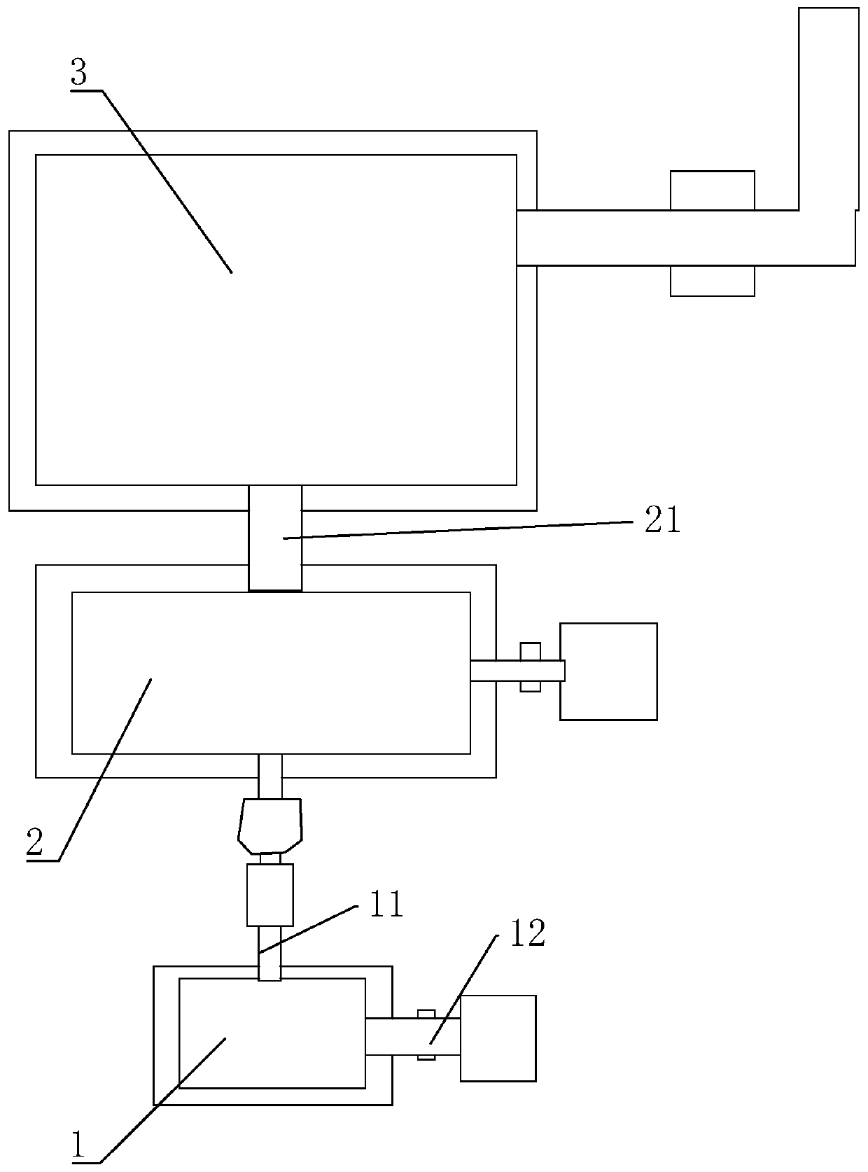
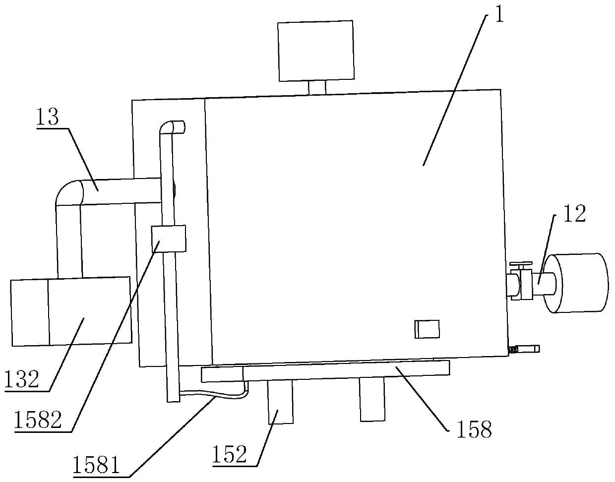
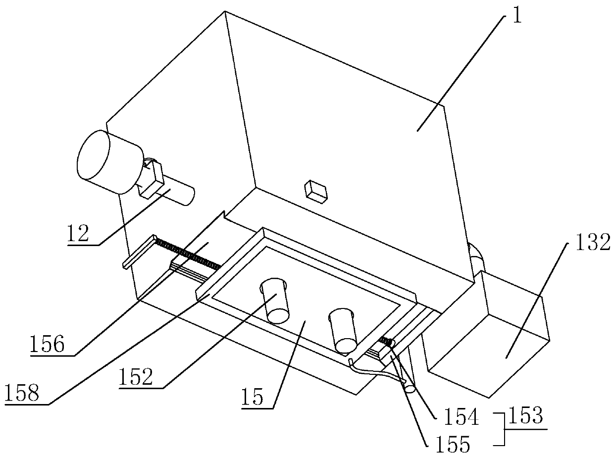
[0032] A catalytic device for exhaust gas treatment, such as figure 1 and figure 2 , including a water-soluble tank 1, a heat exchange tank 2 and a catalytic combustion body 3, a transport pipe 11 is connected to the middle position of the upper end surface of the water-soluble tank 1, and the other end of the transport tube 11 communicates with the heat exchange tank 2, and the upper end surface of the heat exchange tank 2 is connected to the catalytic combustion chamber. An intake pipe 21 is arranged between the bottom end faces of the combustion body 3, and an exhaust gas inlet pipe 12 is connected to one side of the water-soluble tank 1, such as Figure 4 , a solvent pipe 13 is arranged inside the water-soluble tank 1, and branch pipes 131 are evenly arranged on the solvent pipe 13, and the branch pipes 131 communicate with the solvent pipe 13, and the ...


PUM


Abstract

The invention discloses a waste gas treatment catalytic device and relates to the technical field of waste gas treatment devices. The waste gas treatment catalytic device achieves the purposes of clearing impurities in a water solution box and then facilitating the impurities in waste gas to be adsorbed and settled. The key of the technical scheme is that the bottom of the water solution box is provided with a plurality of through holes, the bottom of the water solution box is connected with a seal plate in a sliding manner, the seal plate is provided with connection holes corresponding to thethrough holes, the seal plate is connected with a storage barrel in a threaded manner through the connection holes, and the bottom of the water solution box is provided with a limiting piece limitingthe seal plate from moving.

Description

technical field [0001] The present invention relates to the technical field of exhaust gas treatment equipment, more specifically, it relates to a catalytic device for exhaust gas treatment. Background technique [0002] Catalytic oxidation combustion method is more common in exhaust gas treatment methods. The main principle of catalytic oxidation combustion method is to catalyze the reaction between impurity compounds in exhaust gas by adding catalysts, so that impurity compounds are catalyzed into combustible compounds. The impurities are oxidized to generate water and compounds, or compounds with less pollution, so as to achieve the purpose of waste gas treatment. [0003] In the existing catalytic oxidation equipment, the catalyst is set to carry out catalytic reaction with the exhaust gas before combustion, and a special burner will be installed to support the combustion during combustion. Exchange to warm up. [0004] The Chinese patent with the notification number C...

Claims


Application Information

Patent Timeline
Patent Type & Authority Applications(China)
IPC IPC(8): F23G7/07B01D47/02B01D53/18
CPCB01D47/021B01D53/18F23G7/07F23G2209/14
Inventor 朱立新宋扬朱正华
Owner 南京金帝华阳环境检测有限公司
Why Eureka
Try Eureka