A high water pressure resistant fiber grating temperature sensor and assembly method

A technology of temperature sensor and fiber grating, applied in the direction of thermometers, thermometers, thermometer parts, etc. with physical/chemical changes, can solve the problems of inability to apply, complex manufacturing process, complex structure, etc. Processing difficulty, small size effect

Active Publication Date: 2020-06-23
国能大渡河猴子岩发电有限公司
View PDF8 Cites 0 Cited by
  • Summary
  • Abstract
  • Description
  • Claims
  • Application Information

AI Technical Summary

Problems solved by technology

[0006] The purpose of the present invention is to address the above problems, to provide a fiber grating temperature sensor that is easy to use, simple to connect, has strong protection strength, and can respond quickly to ambient temperature and withstand high water pressure, so as to solve the problem of conventional fiber grating The temperature sensor has a complex structure and a complex manufacturing process, which cannot be applied to the special harsh environment of high water pressure.

Method used


Image

  • A high water pressure resistant fiber grating temperature sensor and assembly method

Examples


Embodiment 1

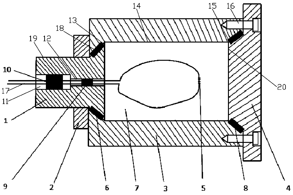
[0033] like figure 1 , a fiber grating temperature sensor resistant to high water pressure, it includes a housing 3, the inside of the housing 3 is provided with an inner cavity 14, the inside of the inner cavity 14 is provided with a fiber grating 5, the fiber grating 5 The optical fiber lead-out line 17 passes through the upper cover 1 and leads out of the housing 3, the upper cover 1 is fixedly installed on one end of the outer housing 3 and seals one side of the inner cavity 14; the end of the outer housing 3 opposite to the upper cover 1 A lower cover 4 for sealing the other side of the inner cavity 14 is installed. By adopting the fiber grating temperature sensor with the above structure, since it is in use, the fiber grating 5 is inside the completely airtight inner cavity 14, and the fiber grating is in a bending and relaxing state in the airtight working cavity, and it will not be compressed nor It will be stretched, avoiding the influence of fiber grating tensile st...

Embodiment 2

[0043] The assembly method of the high water pressure resistant fiber grating temperature sensor described in any one is characterized in that comprising the following steps:

[0044] The first step is to pass the fiber lead-out wire 17 of the fiber grating 5 through the first center hole 12 and the second center hole 11 of the upper cover 1, and make the fiber grating 5 inside the inner cavity 14 in a state of free bending and relaxation After the optical fiber lead-out line 17 is led out of the upper cover 1, the first central hole 12 is dispensed and filled to form the first sealant 9, and the second central hole 11 is dispensed and filled to form the second sealant 10, and the upper cover is ensured 1 sealing of the center hole;

[0045] In the second step, the first sealing ring 6 is installed on the first frustum section 18 of the upper cover 1, and the upper cover 1 with the fiber grating 5 enters the working cavity 7 inside the outer shell 3 through the lower surface o...


PUM

PropertyMeasurementUnit
water pressureaaaaaaaaaa

Abstract

The patent of the present invention relates to a fiber grating temperature sensor with high water pressure resistance and an assembly method, which includes a casing, an inner cavity is arranged inside the casing, an optical fiber grating is arranged inside the inner cavity, and an optical fiber grating is arranged inside the optical fiber grating. The optical fiber lead-out line passes through the upper cover and leads out of the shell. The upper cover is fixedly installed on one end of the shell and seals one side of the inner cavity; Lower cover sealed on one side. It is a fiber grating temperature sensor that is easy to use, simple to connect, has strong protection strength, and can respond quickly to the ambient temperature and withstand high water pressure, so as to solve the problem that the conventional fiber grating temperature sensor has complex structure and complicated manufacturing process, which cannot be applied in High water pressure is a particular problem in harsh environments.

Description

technical field [0001] The invention relates to an optical fiber grating temperature sensor, in particular to a high water pressure resistant optical fiber grating temperature sensor and an assembly method, belonging to the field of optical fiber grating sensor design. Background technique [0002] With the development of the national economy and the improvement of environmental protection requirements, hydropower, as a renewable clean energy, has been widely used. With the advancement of hydropower development technology, there are more and more hydropower stations with high dams and large reservoirs. At present, several hydropower stations with a dam height of 200 meters have been built, and several hydropower stations with a dam height of 300 meters are under construction. These high dams all require that the monitoring instruments buried inside the dam body have the characteristics of high water pressure resistance: for example, the water pressure can reach 5MPa, or eve...

Claims


Application Information

Patent Timeline
Patent Type & Authority Patents(China)
IPC IPC(8): G01K11/32G01K1/08G01K11/3206
CPCG01K11/32G01K1/08
Inventor 袁宏才朱永国郭永兴唐珂
Owner 国能大渡河猴子岩发电有限公司
Why Eureka
Try Eureka