Eureka AIR delivers breakthrough ideas for toughest innovation challenges, trusted by R&D personnel around the world.

Multi-station radar station location and joint tracking method based on distributed PHD

A radar station, distributed technology, applied in the direction of reflection/re-radiation of radio waves, utilization of re-radiation, measurement devices, etc., can solve the problems of poor system robustness, large communication burden, huge communication burden, etc., and achieve fast convergence speed , the effect of small amount of calculation

Active Publication Date: 2019-08-30
UNIV OF ELECTRONICS SCI & TECH OF CHINA
View PDF18 Cites 6 Cited by
  • Summary
  • Abstract
  • Description
  • Claims
  • Application Information

AI Technical Summary

Problems solved by technology

However, this method needs to collect all measurement information from all radars, so in a high-density clutter environment, building a joint likelihood function will cause a huge communication burden, and this method uses a centralized fusion architecture, resulting in The whole system is less robust
In the literature "M.Uney, B.Mulgrew, and D.E.Clark," A Cooperative approach to sensor localization in distributed fusion networks," IEEETrans.Signal Process., vol.64, no.5, pp.1187-1199, Oct.2016 A radar joint tracking and self-localization method based on a posteriori information was proposed in ". However, this method uses high-dimensional particles to represent the local a posteriori, so a large number of particles need to be transmitted between multiple radars to The estimation of the posterior information causes a huge communication burden, and the information transmitted between the sensors uses the belief propagation technology, which is not suitable for the ring multi-sensor network structure

Method used


Image

  • Multi-station radar station location and joint tracking method based on distributed PHD
  • Multi-station radar station location and joint tracking method based on distributed PHD
  • Multi-station radar station location and joint tracking method based on distributed PHD

Examples


Embodiment Construction

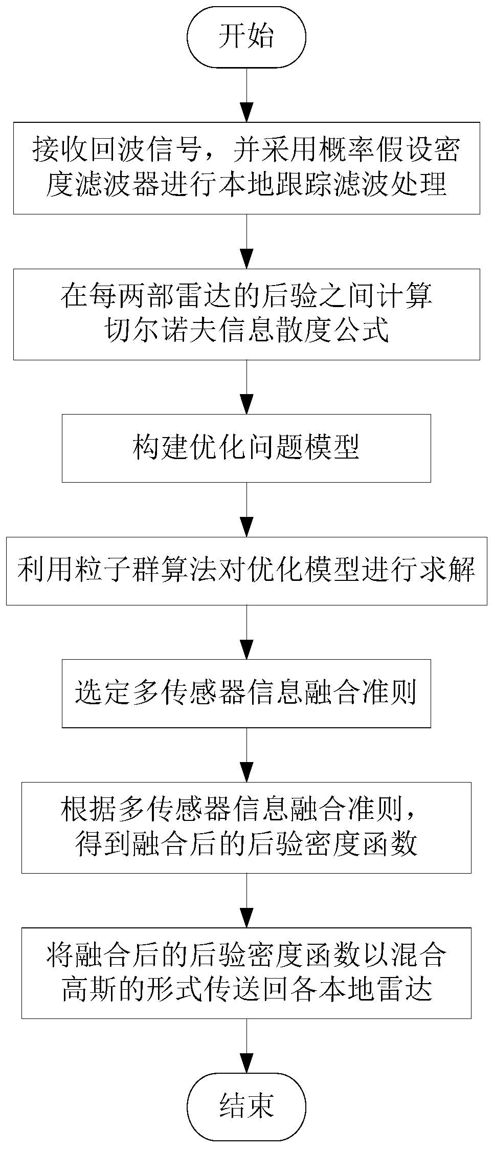
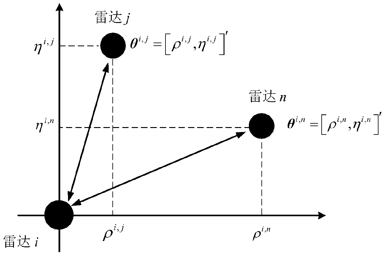
[0048]The solution of the present invention is that in the stage of multi-station radar site positioning, each radar uses PHD filter to perform local filtering and obtain the posterior information represented by the mixed Gaussian form, and then use these posterior information to calculate the distance between each two radars. The Chernoff information divergence of the particle swarm algorithm is used to optimize the Chernoff information divergence to obtain the relative position between each two radars. In the joint tracking stage, according to the obtained relative position of the radar, under the distributed framework, the posterior information is fused by using the generalized covariance intersection criterion, and the joint tracking result is obtained. The technical solution of the present invention will be further described below in conjunction with the accompanying drawings.

[0049] like figure 1 As shown, a multi-station radar site location and joint tracking method ...


PUM


Abstract

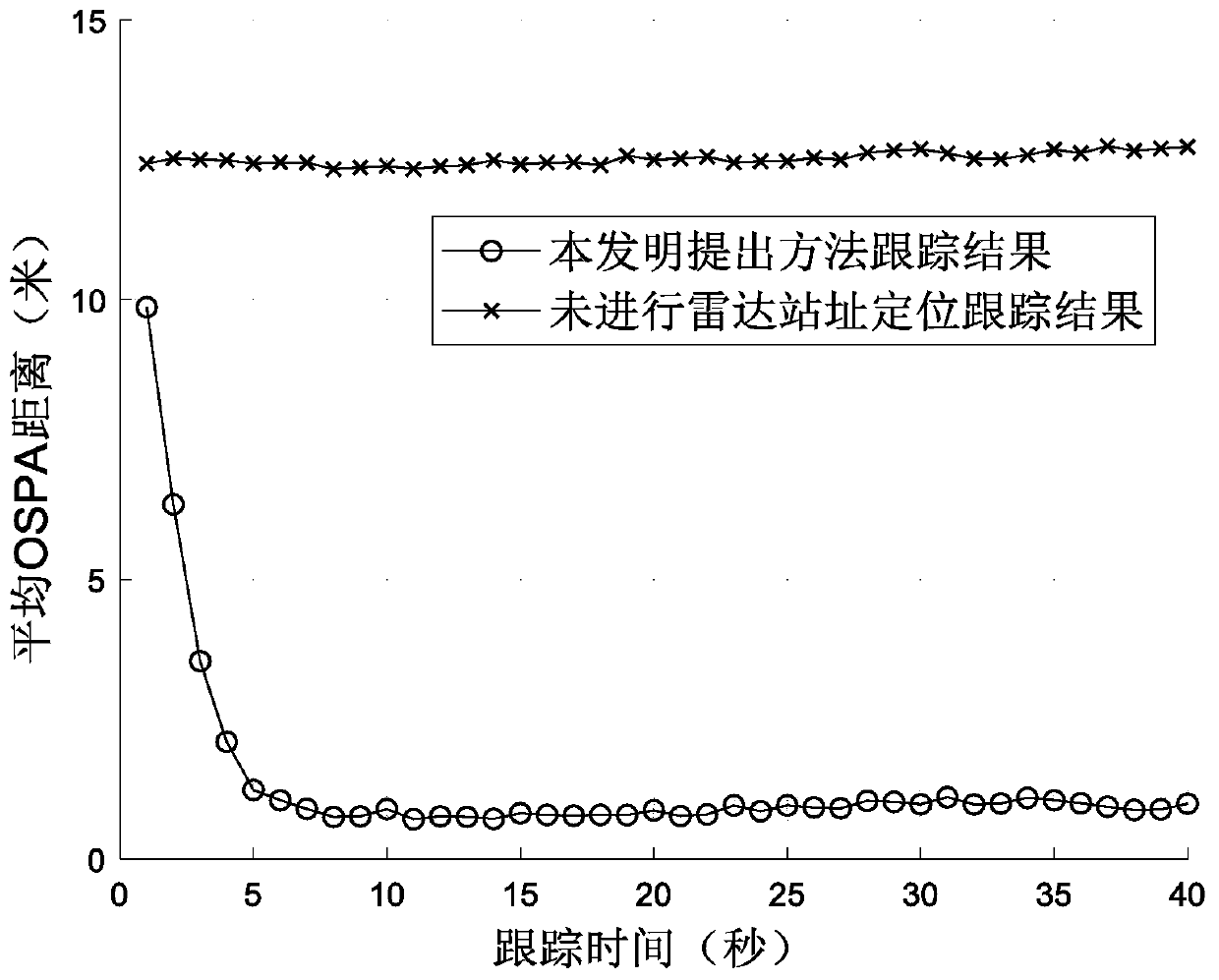
The present invention discloses a multi-station radar station location and joint tracking method based on the distributed PHD (pulse height discrimination). The method comprises the following steps: S1, receiving echo signals, and performing local tracking filtering processing; S2, calculating a Chernoff information divergence formula between posterior in every two radars; S3, constructing an optimization problem model; S4, solving the optimization model, and obtaining position parameters of all radars relative to other radar sites; S5, selecting multi-sensor information fusion criteria; S6, jointing the posterior distribution to change into an edge density function, and obtaining a fused posterior density function according to the multi-sensor information fusion criteria; and S7, transmitting the fused posterior density function back to the local radar in the form of mixed Gaussian. According to the method provided by the present invention, information of the target can be measured bymultiple radars in the case of the unknown multi-station radar precise position, multi-station radar location, multi-target tracking and information fusion can be performed, and the method has a mallcalculation amount, a fast convergence speed, and other characteristics.

Description

technical field [0001] The invention belongs to the technical field of radar target tracking, in particular to a multi-station radar site location and joint tracking method based on distributed PHD. Background technique [0002] In modern warfare, using multi-station radars widely distributed in the combat area to jointly track targets is already a research hotspot in the field of radar tracking. Compared with a single radar, the use of multi-station radar can obtain more dimensions and wider range of information about the target, thereby improving the detection performance of the target and the robustness of the system. When multi-station radars are used to jointly track targets, the precise positions of the multi-station radars need to be known in order to perform operations such as spatial alignment during information fusion. However, in actual scenarios, due to positioning errors and other reasons, the system cannot provide the accurate position of the radar, which lead...

Claims


Application Information

Patent Timeline
IPC IPC(8): G01S13/66
CPCG01S13/66
Inventor 杨晓波柴雷吴若凡杨琪李溯琪易伟孔令讲
Owner UNIV OF ELECTRONICS SCI & TECH OF CHINA
Why Eureka
Eureka Blog
Learn More