Control circuit, backlight driving device and display device

A technology for controlling circuits and resistors, applied in control/regulation systems, adjusting electrical variables, static indicators, etc., can solve problems such as temperature rise, burnout of liquid crystal display devices, abnormal working status of liquid crystal display panels or drive circuits, etc. , to reduce the temperature and prevent the effect of high temperature

Active Publication Date: 2020-12-29
BOE TECH GRP CO LTD +1
View PDF9 Cites 0 Cited by
  • Summary
  • Abstract
  • Description
  • Claims
  • Application Information

AI Technical Summary

Problems solved by technology

[0002] In a liquid crystal display device, both the drive circuit and the backlight will generate a large amount of heat during operation, which will cause the temperature of the liquid crystal display device to rise
When the temperature is too high to a certain height, it may cause the LCD panel or the driving circuit to be in an abnormal working state or even burn out.

Method used


Image

  • Control circuit, backlight driving device and display device
  • Control circuit, backlight driving device and display device
  • Control circuit, backlight driving device and display device

Examples


Embodiment Construction

[0053] Specific embodiments of the present invention will be described in detail below in conjunction with the accompanying drawings. It should be understood that the specific embodiments described here are only used to illustrate and explain the present invention, and are not intended to limit the present invention.

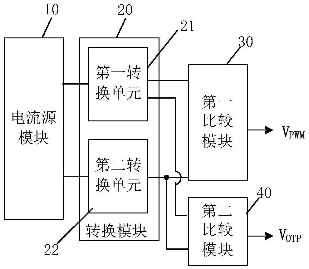
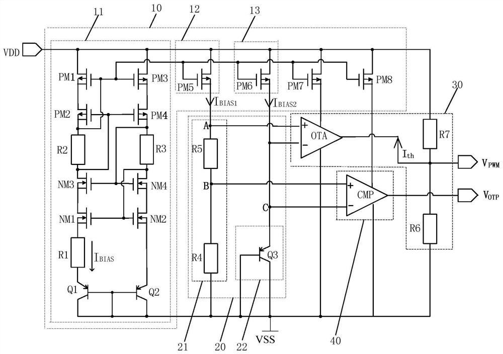
[0054] As an aspect of the present invention, a control circuit is provided, such as figure 1 As shown, the control circuit includes a current source module 10 , a conversion module 20 and a first comparison module 30 . in:

[0055] The current source module 10 is connected to the power supply terminal VDD for generating a current signal whose magnitude is positively correlated with the temperature of the area where the control circuit is located.

[0056] The conversion module 20 includes a first conversion unit 21 and / or a second conversion unit 22, the first conversion unit 21 is used to provide a first voltage signal to the positive input end of the first ...


PUM


Abstract

The present invention provides a control circuit, including a current source module, a conversion module and a first comparison module: the current source module is used to generate a current signal whose magnitude is positively correlated with temperature; the conversion module includes a first conversion unit and / or a second conversion unit , the first conversion unit is used to provide the first voltage signal to the positive input terminal of the first comparison module, and the first voltage signal is positively correlated with the magnitude of the current signal generated by the current source module; the second conversion unit is used to provide the first comparison module The reverse input terminal of the module provides a second voltage signal, and the second voltage signal is negatively correlated with the magnitude of the current signal generated by the current source module; the first comparison module is used to output control when the positive input terminal is greater than the voltage signal of the reverse input terminal signal, the control signal is negatively correlated with the voltage signal difference between the positive input terminal and the negative input terminal of the first comparison module. Correspondingly, the invention also provides a backlight driving device and a display device, and the invention can prevent the temperature of the display device from being too high.

Description

technical field [0001] The invention relates to the field of display technology, in particular to a control circuit, a backlight driving device and a display device. Background technique [0002] In a liquid crystal display device, both the driving circuit and the backlight source generate a large amount of heat during operation, which leads to an increase in the temperature of the liquid crystal display device. When the temperature is too high to a certain height, it may cause the liquid crystal display panel or the driving circuit to be in an abnormal working state or even burn out. Contents of the invention [0003] The present invention aims to solve at least one of the technical problems in the prior art, and proposes a control circuit, a backlight driving device and a display device to prevent the temperature of the display device from being too high. [0004] In order to solve one of the above technical problems, the present invention provides a control circuit, in...

Claims


Application Information

Patent Timeline
Patent Type & Authority Patents(China)
IPC IPC(8): G09G3/34G09G3/36
CPCG09G3/3413G09G3/36G09G3/3406G09G2320/064G09G2320/041G09G2330/045G05F3/30G05F3/225G09G3/3426G09G3/3696G09G5/10
Inventor 胡晔卢晓莹
Owner BOE TECH GRP CO LTD
Why Eureka
Try Eureka