
A display panel, its drive control method, and display device

A technology for display panels and screens, applied in static indicators, instruments, semiconductor devices, etc., can solve problems such as poor crosstalk, pixel crosstalk, and reduced display performance of display panels

Active Publication Date: 2021-08-20
BOE TECH GRP CO LTD +1
View PDF5 Cites 0 Cited by
  • Summary
  • Abstract
  • Description
  • Claims
  • Application Information

AI Technical Summary

Problems solved by technology

During use, it was found that during the working process of the OLED display panel, there will be pixel crosstalk. For example, when the first picture is displayed, the surrounding pixels will light up slightly, resulting in poor crosstalk and reducing the display performance of the display panel.

Method used


Image

  • A display panel, its drive control method, and display device
  • A display panel, its drive control method, and display device
  • A display panel, its drive control method, and display device

Examples


preparation example Construction

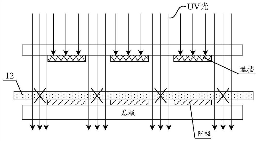
[0075] The embodiment of the present invention also provides a method for manufacturing a display panel, the display panel includes a plurality of OLED pixel regions, and the method includes:

[0076] S1: forming a first electrode and a third electrode located between two adjacent OLED pixel regions on the substrate;

[0077] S2: forming a hole injection layer on the first electrode and the third electrode;

[0078] S3: forming a light-emitting layer located in the OLED pixel region on the hole injection layer;

[0079] S4: forming an electron transport layer on the light-emitting layer;

[0080] S5: forming a second electrode on the electron transport layer.

[0081] The third electrode forms an electric field with the second electrode.

[0082] In one embodiment, the third electrode and the second electrode form a reverse electric field, and the reverse electric field is an electric field opposite to the direction of the electric field between the first electrode and the ...


PUM


Abstract

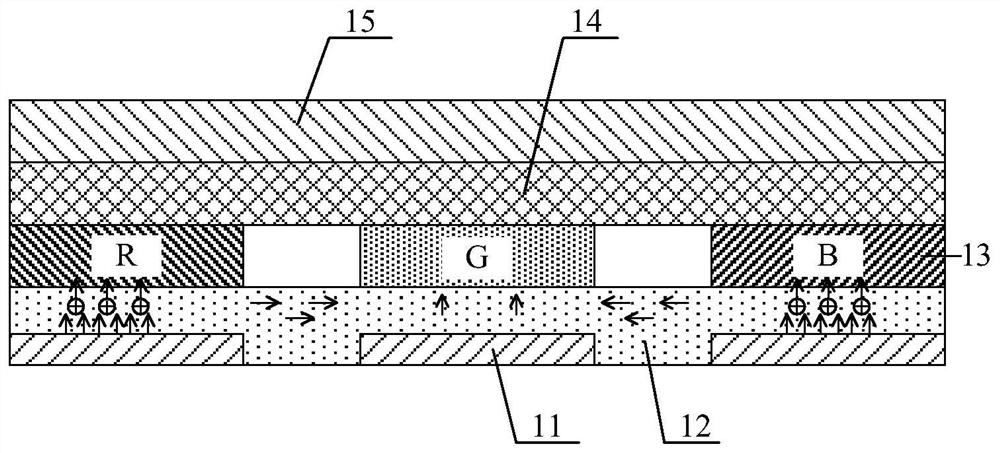
The invention discloses a display panel. The display panel includes a base and a plurality of OLED pixels arranged on the base, and the OLED pixels include a first electrode, a hole injection layer, a light emitting layer, an electron transport layer and a second electrode arranged on the base in sequence The display panel further includes a third electrode disposed between the substrate and the hole injection layer, between two adjacent OLED pixels, and used to form an electric field with the second electrode. The electric field formed between the third electrode and the second electrode can make the holes diffused to the third electrode area diffuse in the vertical direction under the action of the vertical electric field, and suppress the lateral movement of the holes on the hole injection layer, so that Holes cannot diffuse from pixels with high density to pixels with low density, which avoids poor crosstalk.

Description

technical field [0001] The present invention relates to the field of display technology, in particular to a display panel, a driving control method thereof, and a display device. Background technique [0002] Organic Light Emitting Diode (OLED) display panels have attracted much attention in the industry due to their self-illumination, low driving voltage, fast response, and wide viewing angle. The OLED display panel includes a plurality of OLED devices defined by a pixel defining layer, and the OLED device includes an anode, a hole injection layer, an organic light emitting layer, an electron transport layer, a cathode, and the like. [0003] During the fabrication of OLED display panels, each OLED device has an independent organic light-emitting layer to emit specific light as required. Other film layers, such as hole injection layer, electron transport layer, and cathode, are usually common layers, that is, the hole injection layer, electron transport layer, and cathode ...

Claims


Application Information

Patent Timeline
Patent Type & Authority Patents(China)
IPC IPC(8): H01L27/32H01L27/12G09G3/3258
CPCH01L27/1214G09G3/3258G09G2310/0243G09G2320/06H10K59/122
Inventor 徐朝哲李纪梅文娟
Owner BOE TECH GRP CO LTD
Learn More