Steel fiber dispersing machine for preparing fiber concrete

A fiber-reinforced concrete and steel fiber technology, applied in solid separation, screens, grids, etc., can solve the problems of low dispersion efficiency, time-consuming and laborious, and damage to steel fibers, so as to improve dispersion efficiency and avoid bending or damage , to avoid the effect of clogging

Inactive Publication Date: 2019-09-03
SOUTHWEST PETROLEUM UNIV
View PDF9 Cites 13 Cited by
  • Summary
  • Abstract
  • Description
  • Claims
  • Application Information

AI Technical Summary

Problems solved by technology

The artificial dispersion method can only meet the small-scale preparation of fiber concrete in the laboratory. If large-scale concrete construction is carried out, the dispersion efficiency is low, the effect is not ideal, and time-consuming and labor-intensive. Therefore, mechanical dispersion must be used.
Existing conventional dispersing machines include drum type, centrifugal type and sieve drum rotating type, etc. The dispersing blades of the dispersing machine are very easy to bend or damage the steel fibers during dispersion, and the steel fibers are easy to block the grid screen. Dispersed cutting

Method used


Image

  • Steel fiber dispersing machine for preparing fiber concrete
  • Steel fiber dispersing machine for preparing fiber concrete
  • Steel fiber dispersing machine for preparing fiber concrete

Examples


Embodiment 1

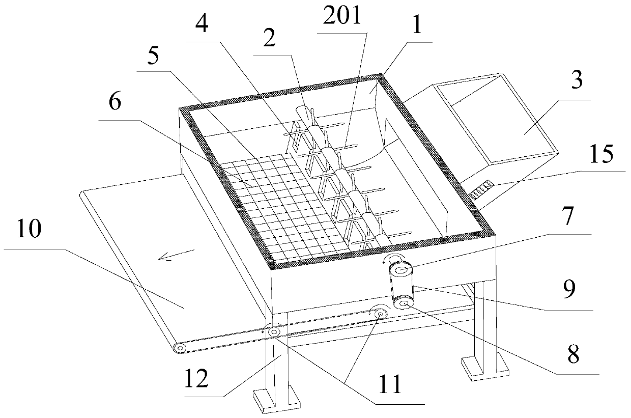
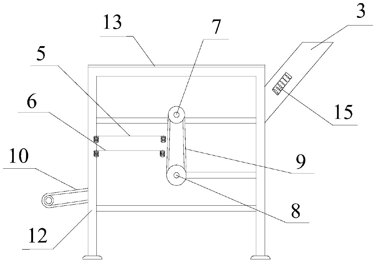
[0035] like Figure 1 ~ Figure 4 As shown, it includes a silo 1 fixed on a bracket 12, a feed hopper 3 is provided on the side wall of the silo 1, a vibrating assembly and a vertically placed partition are included, and the partition divides the material The interior of the warehouse 1 is divided into a feeding chamber and a dispersion chamber. The output port of the feed hopper 3 is connected to the feeding chamber. A feeding device 2 is provided in the feeding chamber, and a discharge port is provided at the bottom of the dispersion chamber. The vibration assembly Fixed on the discharge port; the pusher 2 includes a rotating shaft 7 that is arranged on the wall of the dialing cavity, and a plurality of dialing units are arranged on the outer peripheral wall along the axis of the rotating shaft 7, and the opening on the dividing plate There are a plurality of shifting tooth slots 4 corresponding to the shifting unit, each of which is composed of a plurality of shifting teeth ...

Embodiment 2

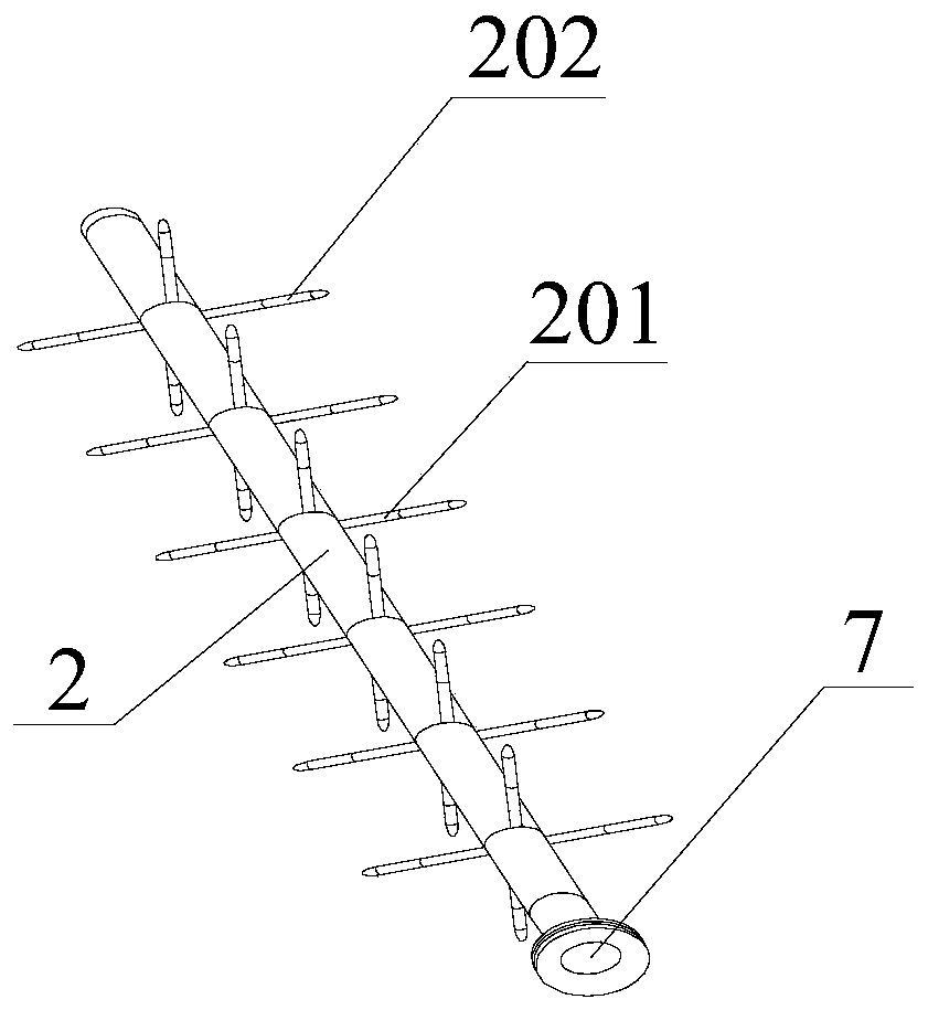
[0043] like Figure 3 ~ Figure 4 As shown, on the basis of Embodiment 1, this embodiment further defines the shifting tooth 201. The shifting tooth 201 is in the shape of a round rod, and one end of the central axis 203 is fixed on the top of the shifting tooth 201. On the outer end face, the roller 202 is sleeved on the central shaft 203 , and the other end of the central shaft 203 is fixed with a tooth tip 204 , and the outer diameter of the tooth tip 204 decreases outward along the radial direction of the rotating shaft 7 .

[0044] The shifting tooth 201 is in the shape of a round rod, and is made of a wear-resistant metal rod, and a central shaft 203 is set on the outer end face of the shifting tooth 201, and a roller 202 is set on the central shaft 203, and the tooth tip 204 is fixed on the central shaft On the end of 203, the roller 202 can rotate freely; in the process that a single shifting tooth 201 drives the steel fiber to transfer from the shifting chamber to the ...

Embodiment 3

[0046] like Figure 5 ~ Figure 6 As shown, the vibrating assembly in this embodiment includes a first vibrating screen 5 and a second vibrating screen 6 placed sequentially from top to bottom, the first vibrating screen 5 includes a rectangular first vibrating screen frame 501, and the second vibrating screen 6 includes a rectangular second vibrating screen frame 601, on the first vibrating screen frame 501 is provided with a plurality of first screen bars 502, and each of the first screen bars 502 and the long side of the first vibrating screen frame 501 Equal length, a plurality of second screen bars 602 are provided on the second vibrating screen frame 601, and each of the second screen bars 602 is equal to the long side of the second vibrating screen frame 601, the first screen bar 502 and the second sieve bars 602 are perpendicular to each other, and a plurality of through holes aligned with the blind holes 504 are opened on the two short sides of the second vibrating scr...


PUM


Abstract

The invention discloses a steel fiber dispersing machine for preparing fiber concrete. The steel fiber dispersing machine comprises a stock bin, wherein a feeding hopper is arranged on the side wall of the stock bin, the interior of the stock bin is divided into a material shifting cavity and a dispersing cavity by a partition plate, an output port of the feeding hopper communicates with the shifting cavity, a shifting device is arranged in the shifting cavity, a material outlet is formed in the bottom of the dispersing cavity, an vibrating assembly is fixed on the material outlet, a pluralityof shifting units are arranged on the periphery outer wall of the rotating shaft along the axis of the rotating shaft, a plurality of shifting tooth grooves are formed in the partition plate, each shifting unit is composed of a plurality of shifting teeth, the rotating shaft is rotated anticlockwise, when the shifting teeth drive the steel fibers to move to the vibrating assembly, and then the shifting tooth penetrate through the material shifting tooth grooves to be moved into the shifting cavity again so as to realize continuous stirring. According to the technical scheme, a conventional latticed screen is not adopted during dispersion, and a two-stage vibrating screen plate is designed, so that secondary dispersion of the steel fibers is realized, and bending or damage of the steel fibers in the dispersing process is avoided while blockage of the steel fibers is avoided.

Description

technical field [0001] The invention relates to a steel fiber disperser, in particular to a steel fiber disperser for preparing fiber concrete. Background technique [0002] Concrete is the most widely used building material in the civil engineering industry. It has the advantages of easy molding, high compressive strength, good durability, and low price. It is widely used in tunnels, bridges, roads, water ports, underground structures, etc. An irreplaceable building material for engineering construction. However, as a brittle building material, concrete's low tensile strength is still a major problem in its engineering application. [0003] The emergence of fiber reinforced concrete has successfully solved the problem of low tensile strength and toughness of concrete. As a high-performance concrete building material, fiber reinforced concrete has been widely used in the field of engineering construction in my country. When fiber-reinforced concrete is prepared, an approp...

Claims


Application Information

Patent Timeline
Patent Type & Authority Applications(China)
IPC IPC(8): B07B1/28B07B1/46
CPCB07B1/28B07B1/46B07B1/4609B07B2201/04
Inventor 张军伟彭鸿健郭亮纪佑军
Owner SOUTHWEST PETROLEUM UNIV
Why Eureka
Try Eureka