Spot plating device and spot plating production line

A technology of spot plating and plating solution, applied in the direction of electrolysis process, electrolysis components, etc., can solve the problems of increased production cost, increased processing procedures, material waste, etc., and achieve the effect of improving accuracy, reducing procedures, and long service life

Pending Publication Date: 2019-09-03
安徽永基电子科技有限公司
View PDF0 Cites 2 Cited by
  • Summary
  • Abstract
  • Description
  • Claims
  • Application Information

AI Technical Summary

Problems solved by technology

[0003] When electroplating electronic components, most of the electroplating equipment used in the prior art is a plating solution tank, and the workpiece is immersed in the plating solution tank for overall electroplating. This method will cause the parts of the parts to be plated that do not need to be electroplated to be electroplated A layer of metal, and the excess electroplating usually needs to be cut off, or the excess plating should be ground off, which not only causes a waste of materials, but also increases the processing procedures, resulting in an increase in production costs

Method used


Image

  • Spot plating device and spot plating production line
  • Spot plating device and spot plating production line
  • Spot plating device and spot plating production line

Examples


Embodiment 1

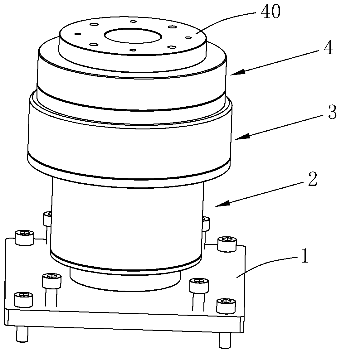
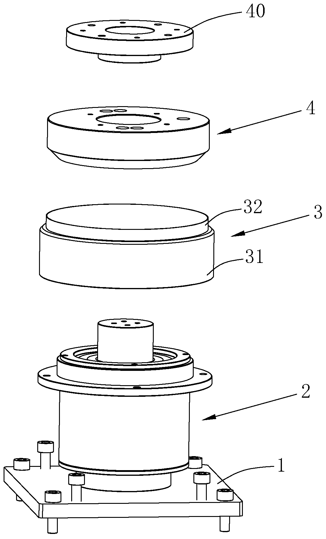
[0052] A spot plating device, with reference to figure 1 and figure 2 , including a rotating mechanism 2, a spot plating wheel 3, a spot plating electrode module 4 and a sealing cover 40.

[0053]Among them, the rotating mechanism 2 is used to support the spot plating wheel 3 to rotate, and is used to fix the spot plating electrode module 4. The spot plating wheel 3 winds the material tape and rotates with the material tape to limit the material tape to the position where spot plating is required. . The sealing cover 40 is used to seal the spot plating electrode module 4 and inject plating solution into the spot plating electrode module 4 . When the electroplating electrode module is continuously spraying, the spot plating wheel 3 drives the material strip to continue to be transported forward, and the next required spot plating position of the material strip is switched along with the electroplating spraying for spraying.

[0054] refer to figure 2 , The spot plating wh...

Embodiment 2

[0072] A spot plating production line, with reference to Figure 7 and Figure 8 , including the spot plating device as in Embodiment 1, and also includes a spot plating support mechanism 8 for conveying the material belt to the spot plating device.


PUM


Abstract

The invention discloses a spot plating device and a spot plating production line, and relates to the field of electroplating. The spot plating device and the spot plating production line comprise a point plating wheel, a spot plating electrode module, a sealing cover and a rotating mechanism, wherein the point plating wheel is arranged to wind a material belt and rotates along with the material belt, the spot plating electrode module is arranged to spray plating solution on the material belt for spot plating, the sealing cover is arranged to seal the spot plating electrode module and inject the plating solution into the spot plating electrode module, and the rotating mechanism is arranged to support the point plating wheel to rotate. The outer side of the spot plating wheel surrounds the material belt, the material belt is continuously conveyed along with the material belt, the spot plating wheel rotates along with the material belt under the support of the rotating mechanism, the material belt is limited to be conveyed at a specific position, meanwhile, the sealing cover seals the spot plating electrode module, the plating solution is continuously injected into the spot plating electrode module, and the spot plating electrode module accurately spray the plating solution on the specific position of the material belt for the spot plating under the action of the pressure of the plating solution, so that the spot plating is more accurate, materials are saved, a coating with excessive spraying is avoided, secondary removal does not exist, the working procedures are reduced, andthe whole point plating process is high in efficiency.

Description

technical field [0001] The invention relates to electroplating technology, more specifically, it relates to a spot plating device and a spot plating production line. Background technique [0002] Electroplating is the process of plating a thin layer of other metals or alloys on the surface of certain metals using the principle of electrolysis. It is a process of using electrolysis to attach a layer of metal film to the surface of metal or other material parts to prevent metal oxidation. Improve wear resistance, electrical conductivity, reflective properties, corrosion resistance and improve appearance. [0003] When electroplating electronic components, most of the electroplating equipment used in the prior art is a plating solution tank, and the workpiece is immersed in the plating solution tank for overall electroplating. This method will cause the parts of the parts to be plated that do not need to be electroplated to be electroplated One layer of metal, and the excess e...

Claims


Application Information

Patent Timeline
IPC IPC(8): C25D5/08C25D5/02
CPCC25D5/08C25D5/026C25D17/00
Inventor 周和平
Owner 安徽永基电子科技有限公司
Why Eureka
Try Eureka