
Labyrinth groove type cooling heat field outer cover

A technology of labyrinth groove and outer cover is applied in the cooling field of thermal field equipment and its accessories, which can solve the problem of thick outer shape of the thermal field cover, and achieve the effects of good cooling effect, improved service life and enhanced cooling effect.

Inactive Publication Date: 2019-09-03
ZHEJIANG UNIV
View PDF6 Cites 0 Cited by
  • Summary
  • Abstract
  • Description
  • Claims
  • Application Information

AI Technical Summary

Problems solved by technology

[0002] With the development of science and technology, all kinds of practical equipment tend to be intelligent and sophisticated, and the thermal field used in the thermal processing industry is becoming more and more efficient and miniaturized. However, the outer cover and its cooling system as the thermal field is isolated from the outside world. It cannot be reduced proportionally, because the cooling system of the thermal field cover still adopts the traditional pipe-type or interlayer spiral cooling, which requires enough space to install water pipes or water barriers, resulting in most of the thermal field cover outside It looks thick, clumsy and heavy in shape. To solve this problem, the present invention designs a thin-walled, labyrinth-trough cooling heat field cover on the basis of the traditional cooling system and combined with advanced machining technology.

Method used


Image

  • Labyrinth groove type cooling heat field outer cover
  • Labyrinth groove type cooling heat field outer cover
  • Labyrinth groove type cooling heat field outer cover

Examples


Embodiment Construction

[0025] The temperature in the thermal field aimed at in this embodiment is as high as 1000~2000 DEG C, and the outer periphery of the thermal field is provided with protective facilities—that is, the thermal field outer cover of the labyrinth trough cooling of the present invention, which is used to prolong the service life of the relevant equipment. It also creates a more suitable working environment for the staff.

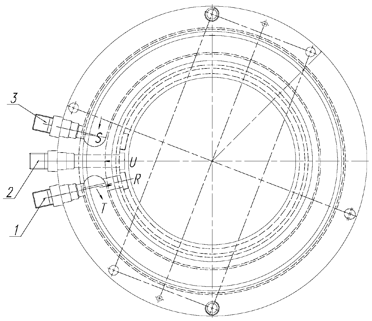
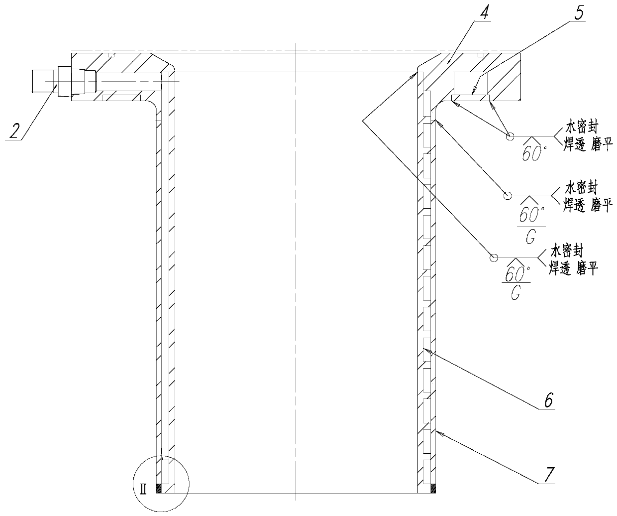
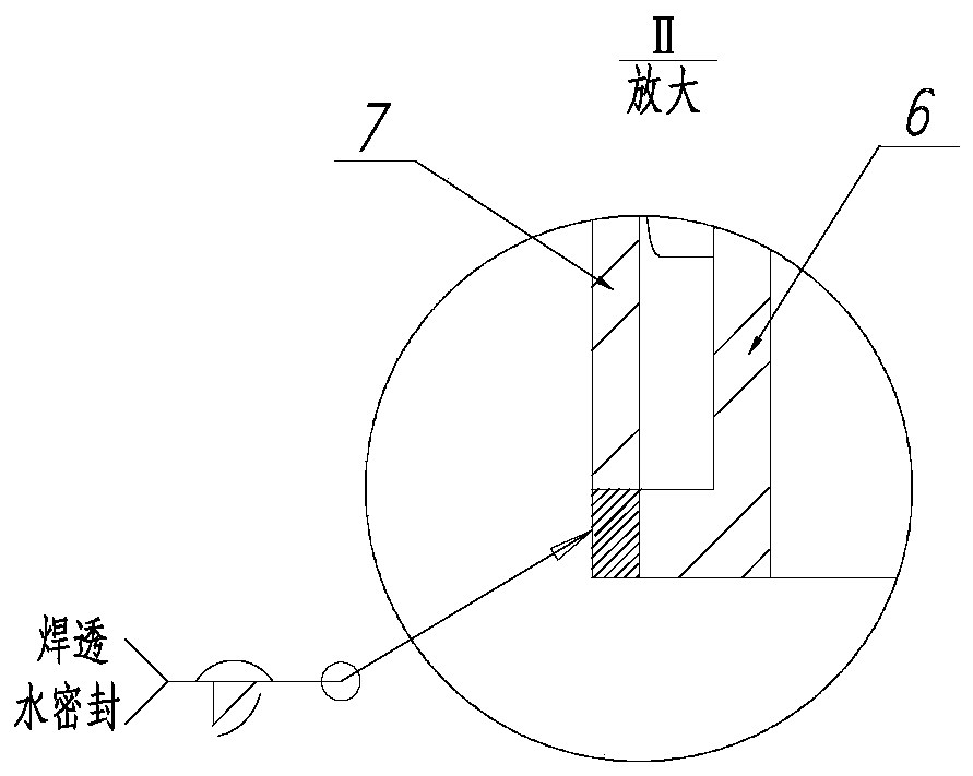
[0026] The heat field outer cover of the labyrinth trough cooling in this embodiment includes a water inlet joint 1, a cylinder return water joint 2, a plate return water joint 3, a flange plate 4, a cover plate 5, an inner tank 6, and a sleeve 7; figure 1 As shown, the water inlet joint 1 is installed in the water inlet 8 on the flange 4; the cylinder return water joint 2 and the plate return water joint 3 are respectively installed in the water outlet 9 and the water outlet 10 on the flange 4 ;like figure 2 As shown, the cover plate 5 is welded on the C-shape...


PUM


Abstract

The invention discloses a labyrinth groove type cooling heat field outer cover. The cover comprises a water inlet connector, a barrel body water return connector, a disc part water return connector, aflange plate, a cover plate, an inner container and a sleeve, wherein the water inlet connector is arranged at a water inlet in the flange plate, the barrel body water return connector and the disc part water return connector are arranged in two water outlets in the flange plate correspondingly, the cover plate is welded on a C-shaped groove at the lower part of the flange plate, the inner container is connected with the flange plate, the end part sof the inner container is welded into an inner hole of the flange plate, the sleeve is arranged outside the inner container, the upper end of thesleeve is welded on the flange plate, the lower end of the sleeve is welded on the lower end of the inner container, a circuitous zigzag channel is formed in the thin wall of the outer cover, a low-temperature water source and a temperature difference can be fully utilized, the cooling effect is enhanced, the service life of equipment is prolonged, and a proper working environment is also createdfor workers. Compared with a traditional cooling system, the thin-wall labyrinth groove type cooling heat field outer cover has the advantages that the cooling effect is better, and the performance ofisolating heat radiation is stronger.

Description

technical field [0001] The invention relates to the cooling of thermal field equipment and its accessories, in particular to a labyrinth groove cooling thermal field outer cover. Background technique [0002] With the development of science and technology, all kinds of practical equipment tend to be intelligent and sophisticated, and the thermal field used in the thermal processing industry is becoming more and more efficient and miniaturized. However, the outer cover and its cooling system as the thermal field is isolated from the outside world. It cannot be reduced proportionally, because the cooling system of the thermal field cover still adopts the traditional pipe-type or interlayer spiral cooling, which requires enough space to install water pipes or water barriers, resulting in most of the thermal field cover outside It looks thick, clumsy and heavy in shape. To solve this problem, the present invention designs a thin-walled, labyrinth-trough cooling heat field cover ...

Claims


Application Information

Patent Timeline
IPC IPC(8): F25D1/02F25D17/02F25D23/02
CPCF25D1/02F25D17/02F25D23/02F25D2323/02
Inventor 韩同春
Owner ZHEJIANG UNIV
Learn More