Plate heater

A heating element and plate-shaped technology, applied in the direction of electric heating devices, ohmic resistance heating, heating element materials, etc., can solve the problems of low heat generation, large current flow, uneven heating, etc., to improve applicability and uniform current flow , the effect of increasing heat

Active Publication Date: 2019-09-03
株式会社参特伦
View PDF10 Cites 0 Cited by
  • Summary
  • Abstract
  • Description
  • Claims
  • Application Information

AI Technical Summary

Problems solved by technology

[0004] However, the current flow at the power input point of the existing plate-shaped heating element is relatively large, so local overheating occurs at the power input point, and the heat generated at the far position between the power input point is relatively low, Therefore, there is a problem of non-uniform heating over the entire surface of the plate-shaped heating element.
Therefore, it is difficult to apply the existing plate-shaped heating element to equipment requiring uniform heating

Method used


Image

  • Plate heater
  • Plate heater
  • Plate heater

Examples


no. 1 example

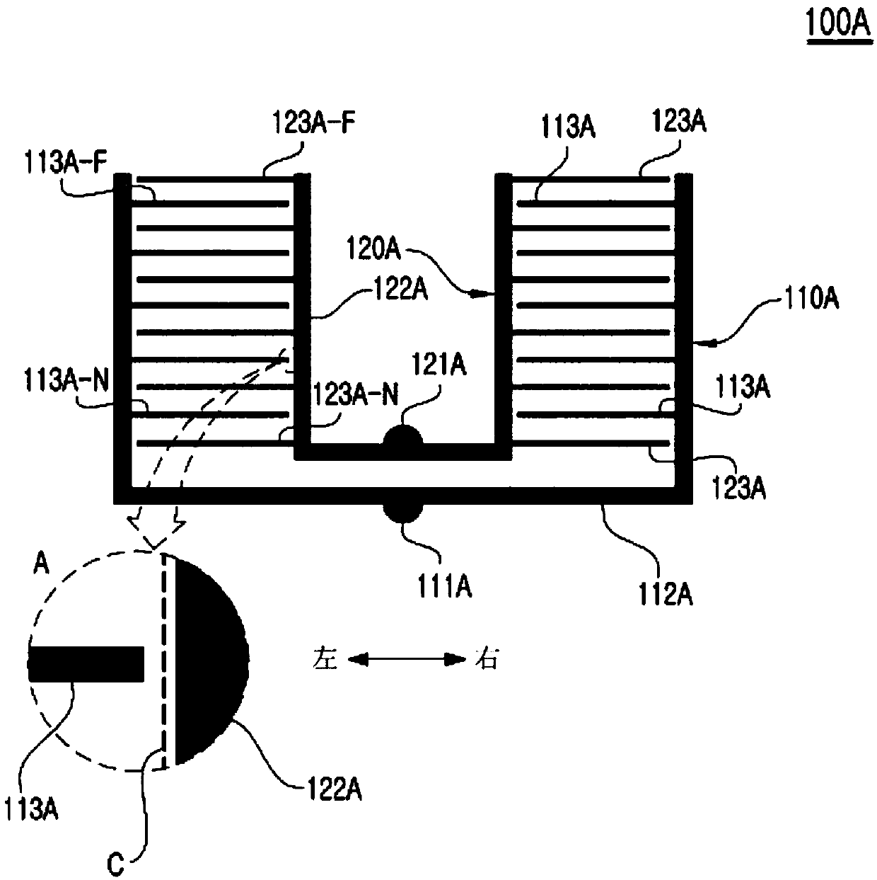
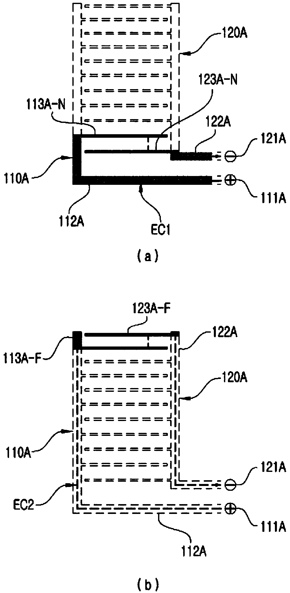
[0059] figure 1 It is a diagram showing an example of the electrode arrangement in the plate-shaped heating element 100A realized as the first embodiment according to the first aspect of the present invention.

[0060] The plate-shaped heating element 100A of this embodiment includes a first electrode 110A and a second electrode 120A that are paired to generate resistance heat to a heating substance.

[0061] The first electrode 110A includes a first power input point 111A, a first main electrode 112A, and a plurality of first bifurcated electrodes 113A.

[0062] The first power input point 111A is connected to the + pole or the-pole of the power source.

[0063] The first main power source 112A is formed to extend in a U-shape in the left-right direction with the first power input point 111A as a reference.

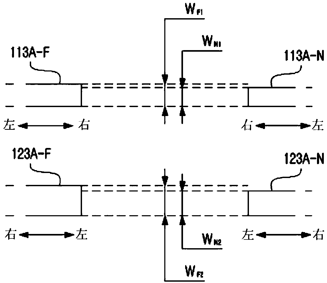
[0064] The plurality of first bifurcated electrodes 113A are bifurcated from the first main electrode 112A and extend in the inner direction, that is, the second electrode 120A si...

no. 3 example

[0086] Figure 5 It is a diagram showing an example of the electrode arrangement of the plate-shaped heating element 300A realized as the third embodiment according to the first aspect of the present invention.

[0087] Figure 5 In the example of, the main electrodes 312A, 322A of the first electrode 310A and the second electrode 320A extend in parallel from different power input points 311A, 321A. Also, the bifurcated electrodes 313A, 323A are alternately arranged from the respective main electrodes 312A, 322A. Here, similarly, the greater the distance from the power input points 311A, 321A, the greater the width of the bifurcated electrodes 313A, 323A.

no. 4 example

[0089] Image 6 It is a diagram showing an example of the electrode arrangement of the plate-shaped heating element 400A realized as the fourth embodiment according to the first aspect of the present invention.

[0090] The plate-shaped heating element 400A according to this embodiment also includes: a first electrode 410A, including a first power input point 411A, a first main electrode 412A, and a first bifurcated electrode 413A; a second electrode 420A, including a second power input point 421A, the second main electrode 422A, and the second bifurcated electrode 423A.

[0091] In this embodiment, the two bifurcated electrodes 413A and 423A are arranged in a circular arc shape. Also, the first power input point 411A and the second power input point 421A are arranged on two sides corresponding to each other on a line L passing through the center O of the bifurcation electrode 413A-L with the largest radius. That is, the first power input point 411A and the second power input poin...


PUM


Abstract

Disclosed herein is a plane heater that generates heat by using graphene or the like as the conductive heat generation material thereof. The plane heater includes: a first electrode configured to be connected to one pole of a power source; and a second electrode configured to be connected to the other pole of the power source; and wherein the intervals between at least some portions of the first electrode and the second electrode are determined such that a plurality of electric circuits formed by the first electrode, the heat generation material, and the second electrode can have the theoretically same resistance, wherein a bridge is disposed to serve as a medium for a current flow between the first electrode and the second electrode. According to the plate heater, current uniformly flowsin a heating substance between the two electrodes for generating uniform resistance heat, thereby improving applicability of the plate heater.

Description

Technical field [0001] The present invention relates to a plate-shaped heating element using graphene or the like as a conductive heating substance. Background technique [0002] Generally, the plate-shaped heating element can be applied to the glass surface of refrigerated display cabinets, window systems, automobile glass surfaces or gaskets, bathroom glass, rice cookers, and the like. [0003] Generally, a plate-shaped heating element is coated with a conductive heating material such as graphene on a non-conductor substrate, and is formed, for example, in a structure in which a first electrode as a + electrode and a second electrode as a-electrode are combined. In addition, if a DC or AC voltage is applied to the first electrode and the second electrode, current flows through the conductive heat generating material to generate resistance heat. [0004] However, the current flow at the power input point of the conventional plate-shaped heating element is relatively large, so local...

Claims


Application Information

Patent Timeline
Patent Type & Authority Applications(China)
IPC IPC(8): H05B3/03H05B3/84
CPCH05B3/03H05B3/84H05B2214/04H05B2203/006H05B3/145H05B3/26H05B3/16
Inventor 金龙基
Owner 株式会社参特伦
Why Eureka
Try Eureka