Hydraulic control device of paddy field rotary tillage and leveling mechanism

A control device and hydraulic technology, which is applied in the fields of tillage implements, agricultural machinery and implements, applications, etc., can solve the problems of decreased working performance of the leveling mechanism, affecting the life of the hydraulic pump, and high temperature of the hydraulic oil, achieving small energy loss and prolonging the service life. , the effect of dynamic response and fast

Inactive Publication Date: 2019-09-06
NANJING AGRICULTURAL UNIVERSITY
View PDF9 Cites 5 Cited by
  • Summary
  • Abstract
  • Description
  • Claims
  • Application Information

AI Technical Summary

Problems solved by technology

[0004] During the working process of the above-mentioned rotary tillage and leveling mechanism in the prior art, the hydraulic pump is basically in a load standby state, which makes it work frequently or continuously, and cannot be unloaded in time, resulting in excessively high hydraulic oil temperature and large power loss. At the same time, it also leads to a decline in the performance of the leveling mechanism, and even affects the life of the hydraulic pump, causing damage to the hydraulic pump.

Method used


Image

  • Hydraulic control device of paddy field rotary tillage and leveling mechanism
  • Hydraulic control device of paddy field rotary tillage and leveling mechanism
  • Hydraulic control device of paddy field rotary tillage and leveling mechanism

Examples


Embodiment 1

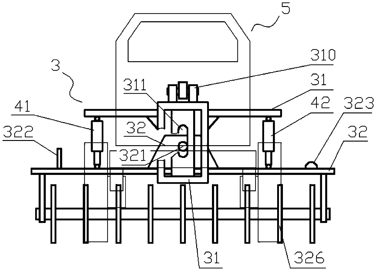
[0024] Such as figure 1 , The hydraulic control device of this embodiment is implemented on the leveling mechanism 3, which has a suspension frame 31, a rotary tillage mechanism frame 32 and two groups of hydraulic cylinders. The suspension frame 31 is suspended and connected with the tractor 5 through the hooking part 310 thereon, and the rotary tillage mechanism frame 32 is connected on the suspension frame 31 so that it can rotate and move up and down relative to the suspension frame. Specifically, a chute 311 is provided on the suspension frame 31, a rotating shaft 321 is provided on the rotary tillage mechanism frame 32, and the rotary tillage mechanism frame 32 is movably connected to the suspension frame 31 through the rotation of the rotary shaft 321 relative to the chute 311 or / and sliding up and down. . Of course, the chute can also be arranged on the rotary tillage mechanism frame 32, and the rotating shaft is arranged on the suspension frame 31. The rotary tillage...

Embodiment 2

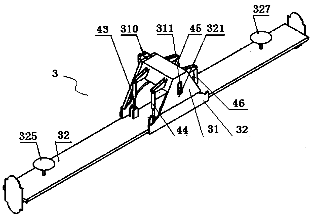
[0036] The hydraulic control device of this embodiment is implemented in such as image 3 On the leveling mechanism 3 shown, the leveling mechanism 3 has the same functional components as in Embodiment 1, including a suspension frame 31, a rotary tillage mechanism frame 32 and two groups of hydraulic cylinders. The suspension frame 31 is suspended and connected with the tractor through a articulated part 310 welded thereto. The symmetrical center of the suspension frame 31 is provided with a chute 311, and the rotary tillage mechanism frame 32 is provided with a rotating shaft 321 matched with the chute 311. The rotating shaft 321 is placed on the sliding In the groove 311 , the frame 32 of the rotary tiller mechanism is movably connected to the suspension frame 31 through the rotation of the rotating shaft 321 relative to the sliding groove 311 or / and sliding up and down. The hydraulic cylinders in this embodiment are placed vertically, and each group includes two hydraulic c...


PUM


Abstract

The invention relates to a hydraulic control device of a paddy field rotary tillage and leveling mechanism. The hydraulic control device comprises a hydraulic loop and a three-position four-way directional valve which controls oil incoming and oil return for hydraulic cylinders. The hydraulic loop includes an oil tank, a hydraulic pump, a one-way valve, an overflow valve, a filter, an accumulatorand a duct; the feed end of the hydraulic pump is connected with the oil tank through the duct and the filter; the discharge end of the hydraulic pump is connected with an oil inlet of the overflow valve and one end of the one-way valve through the duct; the other end of the one-way valve is connected with a remote control port of the overflow valve, forming a hydraulic discharge end; the accumulator is connected with the hydraulic discharge end; the hydraulic pump and the accumulator operate intermittently, so that heat produced due to long-term operation of the hydraulic pump is reduced effectively; dynamic response is fast, and energy loss is low; the three-position four-way directional valve is connected with the corresponding hydraulic cylinder, oil direction and flow are controlled for the corresponding hydraulic cylinder according to a voltage signal so that the hydraulic cylinder expands and changes, and a rotary tillage mechanism frame is driven to move. An electro-hydraulic proportional directional valve helps solve the problem of high reversing impact.

Description

technical field [0001] The invention relates to the field of intelligent agricultural machinery, in particular to a hydraulic control system for a paddy field rotary tillage and leveling mechanism. Background technique [0002] A rotary tiller generally has a number of rotary blades parallel to the blade shaft, and the shaft of the rotary blade is supported on the frame of the rotary tiller. Rotary tillage. Due to the uneven bottom layer of the paddy field, if the height of the knife shaft from the ground is constant, the rotary tiller cannot work on the ground with a concave surface, and the rotary tiller on the ground with a convex surface will be damaged due to the large resistance. Vibration and inclination seriously affect the quality and efficiency of rotary tillage operations, and cannot achieve paddy field leveling operations, which is not conducive to paddy field irrigation, fertilization and the growth of rice crops. Flat paddy fields are conducive to the advance...

Claims


Application Information

Patent Timeline
Patent Type & Authority Applications(China)
IPC IPC(8): A01B33/02A01B33/08
CPCA01B33/02A01B33/08A01B33/087
Inventor 周俊许建康张颖华梁友斌
Owner NANJING AGRICULTURAL UNIVERSITY
Why Eureka
Try Eureka