Reinforcing steel bar bending machine

A bending machine and steel bar technology, applied in the field of steel bar bending machine, can solve the problems of heavy weight, laborious manual movement, etc., and achieve the effect of small size, stable operation and simple structure

Inactive Publication Date: 2019-09-06
李林
View PDF9 Cites 6 Cited by
  • Summary
  • Abstract
  • Description
  • Claims
  • Application Information

AI Technical Summary

Problems solved by technology

Since the length of each steel bar is often relatively long and the weight is relatively heavy, it is laborious to move manua

Method used


Image

  • Reinforcing steel bar bending machine
  • Reinforcing steel bar bending machine
  • Reinforcing steel bar bending machine

Examples


Embodiment 1

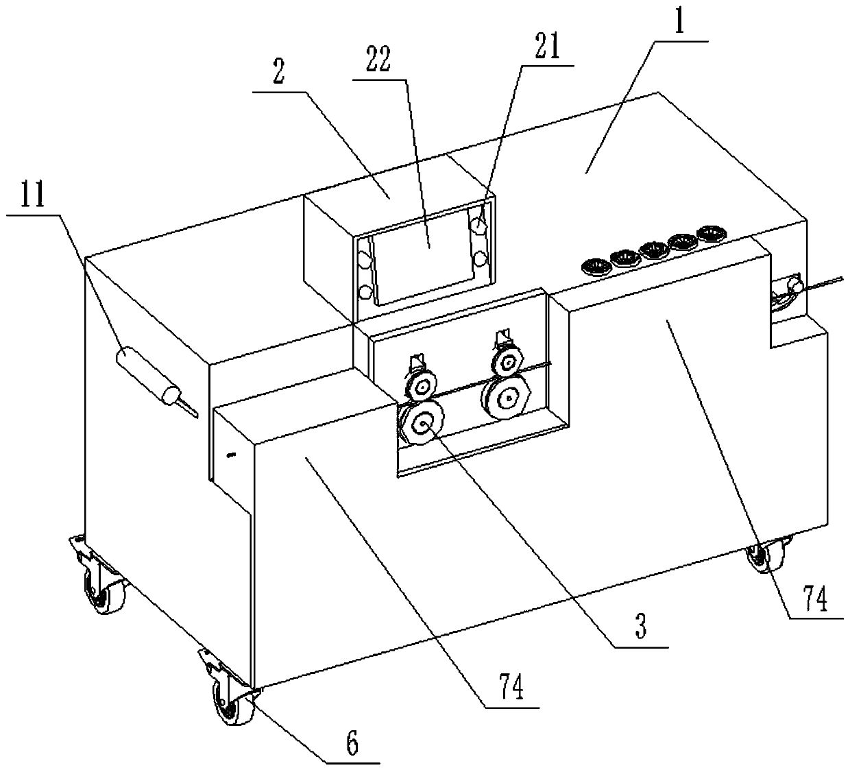
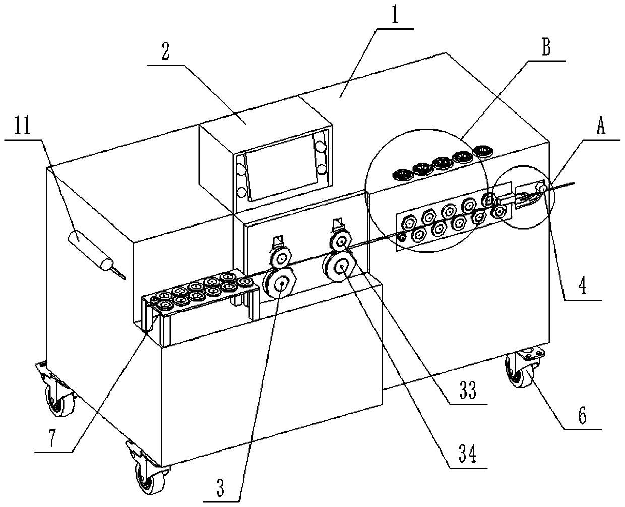
[0056] A steel bar bending machine, comprising a chassis, a control box, a conveying assembly, a bending assembly and a cutting assembly, the control box, the conveying assembly, the bending assembly and the cutting assembly being arranged on the chassis;

[0057] The control box includes a controller, an input device and a display device; the input device and the display device are integrated.

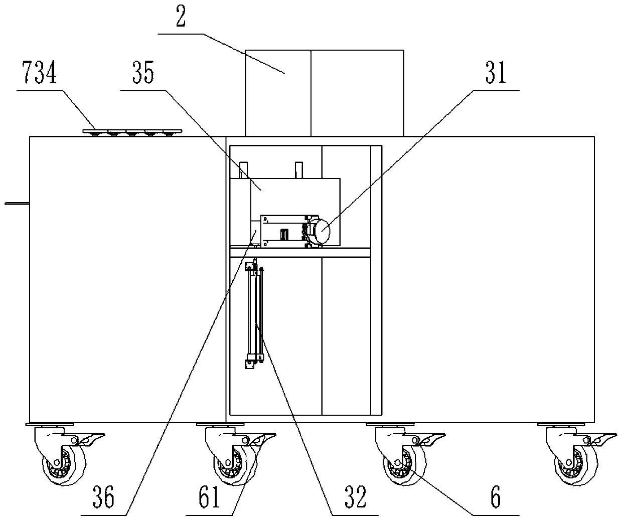
[0058] The conveying assembly includes a conveying motor, a clamping reciprocating part, and a clamping wheel and a feeding wheel arranged up and down. The conveying motor drives the feeding wheel to rotate, and the clamping reciprocating part drives the clamping wheel to reciprocate; the clamping The wheel is arranged directly above the feeding wheel; the clamping wheel and the feeding wheel have two groups, and the feeding wheel of the two groups is connected with the conveying motor through a synchronous gearbox; reducer.

[0059] The bending assembly includes a bending motor, a b...

Embodiment 2

[0069] A steel bar bending machine, including a chassis, a conveying assembly, a bending assembly and a cutting assembly, the conveying assembly, bending assembly and cutting assembly are arranged on the chassis;

[0070] The conveying assembly includes a conveying motor, a clamping reciprocating part, and a clamping wheel and a feeding wheel arranged up and down. The conveying motor drives the feeding wheel to rotate, and the clamping reciprocating part drives the clamping wheel to reciprocate; the clamping The wheel is arranged directly above the feeding wheel; the clamping wheel and the feeding wheel have two groups, and the feeding wheel of the two groups is connected with the conveying motor through a synchronous gearbox; reducer.

[0071] The bending assembly includes a bending motor, a bending shaft and a top block, the bending motor drives the bending shaft to move, the top block is located between the bending shaft and the conveying assembly; the top block is provided...


PUM


Abstract

The invention relates to the technical field of building machinery and in particular to a reinforcing steel bar bending machine. The reinforcing steel bar bending machine comprises a control box, a conveying assembly, a bending assembly and a cut-off assembly. The control box comprises a controller. The conveying assembly comprises a conveying motor, a clamping reciprocating part, a clamping wheeland a feeding wheel. The conveying motor drives the feeding wheel to rotate, and the clamping reciprocating part drives the clamping wheel to move in a reciprocating manner; the bending assembly comprises a bending motor, a bending shaft and an ejector block. The bending motor drives the bending shaft to move, and the ejector block is located between the bending shaft and the conveying assembly;a bending port is formed in the ejector block; the cut-off assembly comprises a cut-off reciprocating part and a cutter, a cut-off port is formed in the ejector block, and the cut-off reciprocating part drives the cutter to move in the cut-off port; and the conveying motor, the clamping reciprocating part, the bending motor and the cut-off reciprocating part are electrically connected to a controller, separately. By arranging the control box, a reinforcing steel bar is conveyed, bended and cut-off integrally automatically.

Description

technical field [0001] The invention relates to the technical field of construction machinery, in particular to a steel bar bending machine. Background technique [0002] Concrete beams and columns or floor slabs require a large number of steel bars, and most of the ends of the steel bars need to be bent to strengthen the anchorage. In traditional bending, the raw material steel bar is in the shape of a disc, and the steel bar needs to be straightened and cut by a straightening machine first, and then bent. This kind of construction is still suitable for steel bars with small quantity, small diameter and low strength. For steel bars with large quantity, large diameter and high strength, the traditional method is labor-intensive and low in construction efficiency. Bending machine to carry out. [0003] There are many types of steel bar bending machines on the market, most of which are fixed installation of the bending machine, the head of the steel bar is inserted into the ...

Claims


Application Information

Patent Timeline
IPC IPC(8): B21F1/00B21F1/02B21F11/00B21F23/00
CPCB21F1/004B21F1/02B21F11/00B21F23/00
Inventor 李林
Owner 李林
Why Eureka
Try Eureka