
Charging device of rail vehicle and rail transit system

A rail vehicle and charging device technology, which is applied in the field of rail vehicles, can solve the problems of heavy weight, complex contactor structure, and unsuitability for rail vehicles, and achieve the effect of simple structure and convenient operation

Active Publication Date: 2019-09-06
BYD CO LTD
View PDF10 Cites 1 Cited by
  • Summary
  • Abstract
  • Description
  • Claims
  • Application Information

AI Technical Summary

Problems solved by technology

[0003] In the related technology, the new energy vehicle adopts a groove on the road surface to charge the vehicle. The technical solution is actually a concave arc surface groove installed under the road surface groove, and the receiver is charged in contact with the arc surface groove. The charging current contactor has complex structure and heavy weight, which affects the cruising range of the car body, and this technical solution is not suitable for use on rail vehicles

Method used


Image

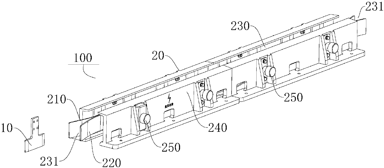
  • Charging device of rail vehicle and rail transit system
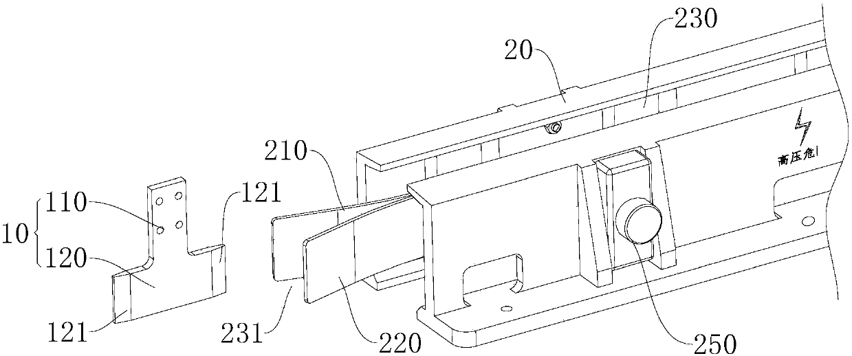
  • Charging device of rail vehicle and rail transit system
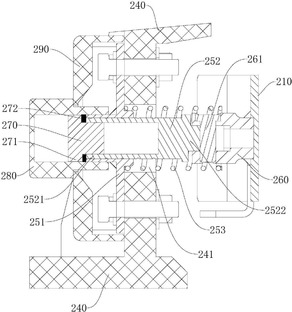
  • Charging device of rail vehicle and rail transit system

Examples


Embodiment Construction

[0047]Embodiments of the present invention are described in detail below, examples of which are shown in the drawings, wherein the same or similar reference numerals designate the same or similar elements or elements having the same or similar functions throughout. The embodiments described below by referring to the figures are exemplary only for explaining the present invention and should not be construed as limiting the present invention.

[0048] In describing the present invention, it should be understood that the terms "length", "thickness", "upper", "lower", "front", "rear", "left", "right", "inner", " The orientation or positional relationship indicated by "outside", etc. is based on the orientation or positional relationship shown in the drawings, and is only for the convenience of describing the present invention and simplifying the description, rather than indicating or implying that the referred device or element must have a specific orientation, so as to Specific o...


PUM


Abstract

The invention discloses a charging device of a rail vehicle and a rail transit system. The charging device of the rail vehicle comprises a charging knife and charging rails; the charging knife is electrically connected with an energy storage device of the rail vehicle; the charging rails comprise first charging boards and second charging boards; the first charging boards and the second charging boards are arranged in a spaced manner to construct a groove body; and the first charging boards and the second charging boards both comprise multiple sections of section boards which are electrically connected with each other in sequence in the running direction of the rail vehicle. According to the charging device of the rail vehicle, when the charging knife enters into the groove body, the charging knife is electrically connected with the first charging boards and the second charging boards to charge the energy storage device of the rail vehicle. Moreover, the multiple sections of section boards can prolong the contacting distances between the charging knife and the first charging boards and the contacting distances between the charging knife and the second charging boards, and thereforethe rail vehicle can be enabled to charge enough electric quantity into the energy storage device in the running process.

Description

technical field [0001] The invention relates to the technical field of rail vehicles, in particular, to a charging device for rail vehicles and a rail transit system. Background technique [0002] Rail vehicles usually use flexible catenary to take power, and use pantograph-catenary or shoe-rail contact charging. This power-taking method arranges power grids along the entire line, and the investment cost of power-taking methods is generally high. The development potential of transport electric locomotives is huge. [0003] In the related technology, the new energy vehicle adopts a groove on the road surface to charge the vehicle. The technical solution is actually a concave arc surface groove installed under the road surface groove, and the receiver is charged in contact with the arc surface groove. The charging current receiving contactor is complex in structure and heavy in weight, which affects the cruising range of the car body, and this technical solution is not suitab...

Claims


Application Information

Patent Timeline
Patent Type & Authority Applications(China)
IPC IPC(8): B60L53/14B60L53/16B60M1/34
CPCB60M1/34B60L2200/26B60L53/14B60L53/16B60L5/40H01R11/12B60L5/38Y02T10/70Y02T90/14Y02T10/7072
Inventor 尹双曾海飞裘骏刘秀
Owner BYD CO LTD
Learn More