
Asphalt heating heat exchanger

A technology of heat exchanger and heater, which is applied in the processing of tar pitch/petroleum pitch/natural pitch, heating processing of tar pitch/petroleum pitch/natural pitch, petroleum industry, etc., which can solve the problem of slow heating speed and low heating efficiency , Inconvenient asphalt temperature and other problems, to achieve the effect of increasing speed and improving heating efficiency

Pending Publication Date: 2019-09-06
河北交科材料科技有限公司
View PDF0 Cites 2 Cited by
  • Summary
  • Abstract
  • Description
  • Claims
  • Application Information

AI Technical Summary

Problems solved by technology

[0002] Before the production of modified asphalt, the asphalt matrix needs to be heated, and then transported to the equipment for producing modified asphalt. The existing asphalt heating method is generally: the asphalt is passed into the inside of the tank, and the heat conduction oil pipe located inside the tank is used to heat the tank. Heating the asphalt in bulk, this heating method has a slow heating speed, the asphalt stays in the tank for a long time, and the heating efficiency is low, and the heating speed near the heat transfer oil pipe is fast, and the heating speed of the asphalt far away from the heat transfer oil pipe is slow, resulting in the asphalt in the tank The heating temperature is uneven, and it is not convenient to control the temperature of the asphalt through the heat conduction oil pipe

Method used


Image

  • Asphalt heating heat exchanger
  • Asphalt heating heat exchanger
  • Asphalt heating heat exchanger

Examples


Embodiment 1

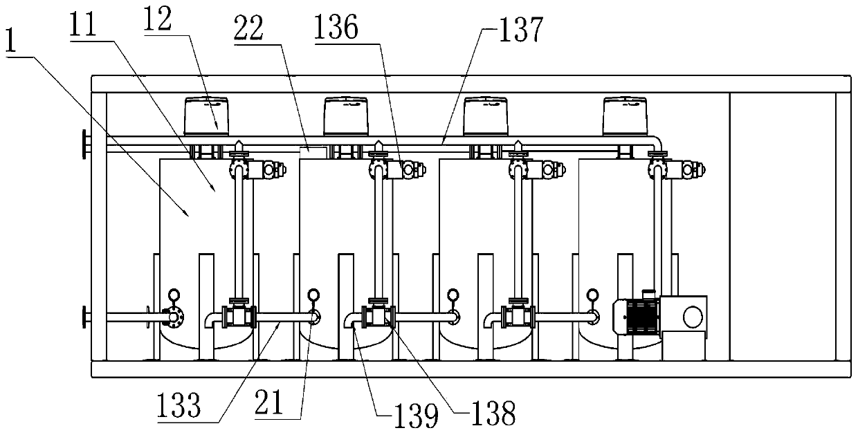
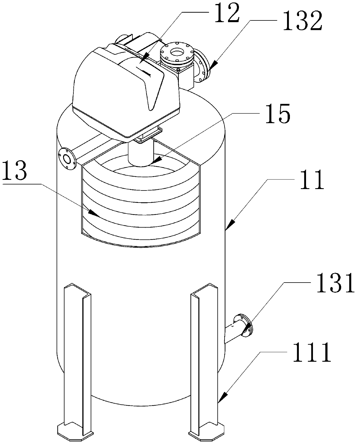
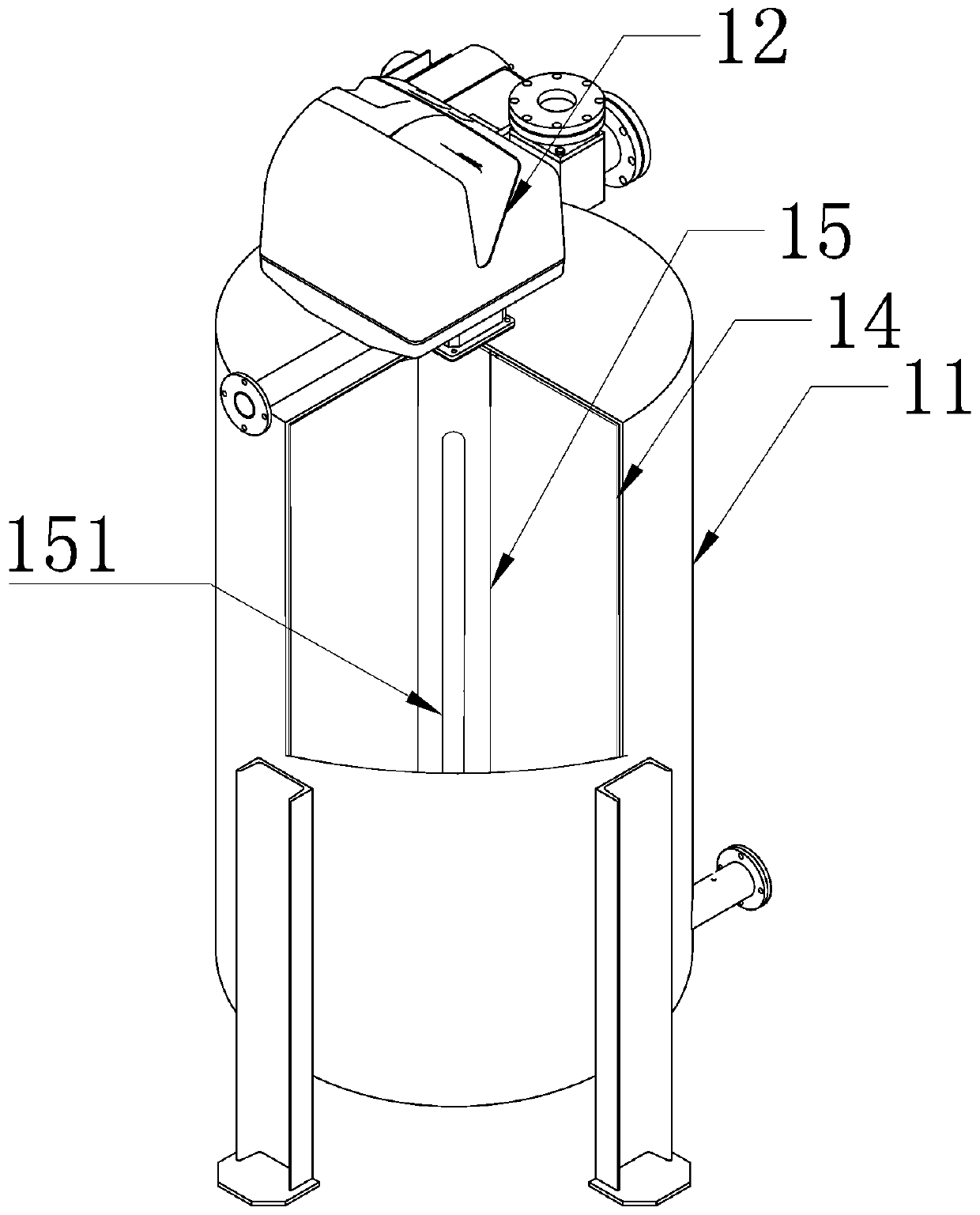
[0027] Such as Figure 1 ~ Figure 3 As shown, the asphalt heating heat exchanger includes a plurality of sequentially connected heating devices 1 and a temperature control device arranged between two adjacent heating devices 1; the heating device 1 includes a tank body 11, a heater 12 and a The asphalt pipeline 13 for transporting asphalt; the inside of the tank 11 is hollow and covered with an insulating layer 14 on the tank wall; the heater 12 is fixed on the top of the tank 11, and the heating body 15 of the heater 12 is located in the tank The middle part of the body 11; the asphalt pipeline 13 is located inside the tank body 11, and the asphalt pipeline 13 is a spiral coil structure; the inlet 131 at the lower end of the asphalt pipeline 13 and the outlet 132 at the upper end both pass through the tank body 11 to the outside, And the inlet 131 and the outlet 132 are all fixed with the tank body 11; the adjacent two heating devices 1, wherein, the outlet 132 of the asphalt...

Embodiment 2

[0037] Such as Figure 4 As shown, on the basis of Embodiment 1, the asphalt pipeline 13 can also be a plurality of standpipes 16 arranged vertically and equidistantly along the circumferential direction of the tank body 11, and the upper and lower ends of the standpipes 16 extend To the outside of the tank body 11, and the end of the standpipe 16 is connected into a pipeline by means of an elbow 17, and the elbow 17 and the standpipe 16 are fixed by means of a detachable connection structure; The first flange 161 and the second flange 171 fixed on the riser 16; the first flange 161 and the second flange 171 are connected by bolts.

[0038] The asphalt pipeline 13 can also be a plurality of standpipes 16 arranged vertically and equidistantly along the circumferential direction of the tank body 11, and the ends of the standpipes 16 are connected into a pipeline with a detachable connection structure by means of an elbow 17. On the basis that the asphalt in the asphalt pipeline...


PUM


Abstract

The invention discloses an asphalt heating heat exchanger. According to the asphalt heating heat exchanger, asphalt pipelines in heating devices are used for conveying asphalt, heaters can heat the asphalt in the asphalt pipelines, and the asphalt pipeline is a spiral coil structure, such that the heating body of the heater can uniformly heat the asphalt in the asphalt pipeline, and the asphalt can be heated while being transported by the asphalt pipeline so as to increase the heating efficiency of the asphalt; through a plurality of the sequentially communicated heating devices, when the asphalt is heated, heating can be performed in a temperature-increasing manner, such that the condition that the one-time heating can cause the non-uniform heating of the asphalt so as to affect the heating effect can be prevented; and temperature control devices between the two adjacent heating devices are used for controlling the communication / disconnection of the communication pipes between the twoadjacent heating devices so as to conveniently control the uniform heating of the asphalt to a certain temperature, and if the asphalt temperature reaches the requirement, the heater after the temperature control device is closed. With the asphalt heating heat exchanger of the present invention, the temperature of the asphalt in the asphalt pipeline can be conveniently controlled.

Description

technical field [0001] The invention relates to the field of modified asphalt processing equipment, in particular to an asphalt heating heat exchanger. Background technique [0002] Before the production of modified asphalt, the asphalt matrix needs to be heated, and then transported to the equipment for producing modified asphalt. The existing asphalt heating method is generally: the asphalt is passed into the inside of the tank, and the heat conduction oil pipe located inside the tank is used to heat the tank. Heating the bitumen in bulk, this heating method has a slow heating speed, the asphalt stays in the tank for a long time, and the heating efficiency is low, and the heating speed near the heat transfer oil pipe is fast, and the heating speed of the asphalt far away from the heat transfer oil pipe is slow, resulting in the asphalt in the tank The heating temperature is uneven, and it is not convenient to control the temperature of the asphalt through the heat conducti...

Claims


Application Information

Patent Timeline
Patent Type & Authority Applications(China)
IPC IPC(8): C10C3/00
CPCC10C3/002
Inventor 赵金龙相宏伟张金柱陈向阳张紫恒李帅赵云
Owner 河北交科材料科技有限公司
Learn More