Novel position encoder

An encoder and a new type of technology, applied in the field of position encoders, can solve the problems of low accuracy, sensor dead zone, and low output value accuracy, and achieve the effect of removing interference noise and high detection accuracy

Pending Publication Date: 2019-09-06
EAST CHINA JIAOTONG UNIVERSITY
View PDF0 Cites 5 Cited by
  • Summary
  • Abstract
  • Description
  • Claims
  • Application Information

AI Technical Summary

Problems solved by technology

Among them, the photoelectric encoder mainly uses the principle of Moiré fringes. When the main grating disk rotates, the light-emitting device will generate Moiré fringes through the main and auxiliary gratings, and the generated Moiré fringes will be sensed by the light receiving element, and then converted into corresponding electrical signals. , and the engraved lines on the grating plate of the sensor cause the photosensitive receiving element to be discontinuous, and the accuracy is low when measuring very precise parts; the potentiometer changes the output resistance value by sliding the brush on the resistor body, It is a process of continuous change, but the brush and the resistor are in contact, and there is mechanical wear between the two, which is prone to jumping points, resulting in low accuracy of the output value; the magnetic encoder is generated by the change of the magnetic field induced by the magnetic sensitive element. A sensor for measuring angular position changes, in which the magnetic sensitive element and the processing circuit are fixed, the magnetic grid acts as a rotor and rotates with the fixed axis of the system, the magnetic sensitive element and the magnetic grid move relative to each other, and the magnetic sensitive element senses the magnetic field at different positions on the magnetic grid Intensity, while the change of the magnetic field strength is manifested as the change of the resistance of the sensitive element, and the change of the voltage is finally used as the output through the conversion process, so as to detect the information such as the rotational position and speed of the system
The magnetic grid used by the sensor is composed of multiple magnetic pole pairs, and there is a certain gap between the magnetic pole pairs, resulting in a certain dead zone in the sensor.

Method used


Image

  • Novel position encoder
  • Novel position encoder
  • Novel position encoder

Examples


Embodiment Construction

[0020] The present invention will be described in further detail below in conjunction with the embodiments and with reference to the accompanying drawings.

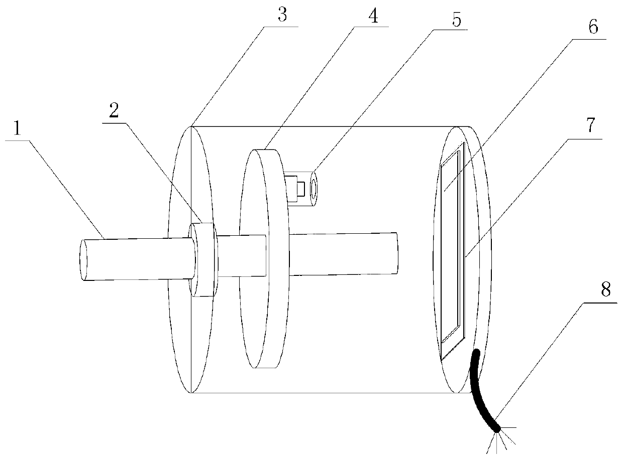
[0021] see Figure 1 to Figure 4 Shown is a new type of position encoder in the present invention, including a rotating shaft, a bearing, a housing, a rotating disk, an optical system, a position detector, a signal processing circuit board, and a signal line.

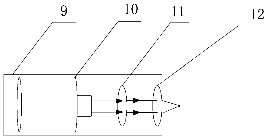
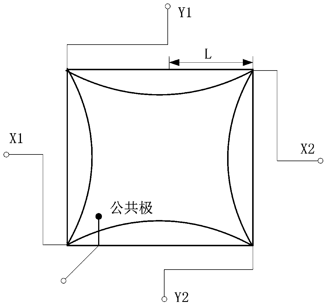
[0022] Such as figure 1 As shown, the bearing 2 is fixed on the top center of the casing 3, the rotating shaft 1 is installed on the bearing 2, and does not contact the bottom of the casing 3, the rotating disk 4, the optical system 5, the position detector 6, and the signal processing circuit board 7 is installed in the casing 3, wherein the rotating disc 4 is fixed on the rotating shaft 1 and rotates with the rotating shaft 1, and the optical system 5 is installed under the rotating disc 4 to emit light spots to the position detector 6, and the position detector...


PUM


Abstract

The invention discloses a novel position encoder, which is composed of a rotating shaft, a bearing, a casing, a rotating disk, an optical system, a position detector, a signal processing circuit boardand a signal line. The rotating disk is driven to rotate through rotating the rotating shaft, the optical system rotates, a laser beam emitted by a laser emitter in the optical system passes througha convex lens and forms a spot, the spot is incident on the photosensitive surface of the position detector, and when the position detector detects the spot emitted by the laser emitter moves along with the rotating shaft, the output end generates corresponding photocurrent signals, and the signals are processed by the signal processing circuit board to obtain corresponding voltage signals, the signals are transmitted out through the signal line, and a user can receive the signals conveniently.

Description

technical field [0001] The invention relates to the field of position encoders, in particular to a novel position encoder. Background technique [0002] With the development of science and technology, the standards for products in many industries have also increased, requiring higher precision assembly parts. Among them, the encoder is one of the commonly used sensors in the numerical control system, and the numerical control system needs to be equipped with a high-precision encoder in order to obtain accurate data information. Especially in aviation, aerospace, military, railway and other fields, it plays a very critical role. Therefore, improving the resolution and precision of the encoder plays an important role in the development of precision measurement technology. [0003] At present, the common position encoders include photoelectric encoders, potentiometers, and magnetic encoders. Among them, the photoelectric encoder mainly uses the principle of Moiré fringes. Wh...

Claims


Application Information

Patent Timeline
Patent Type & Authority Applications(China)
IPC IPC(8): G01D5/347
CPCG01D5/3473
Inventor 刘子英张靖谢瑞
Owner EAST CHINA JIAOTONG UNIVERSITY
Why Eureka
Try Eureka