
Sensor circuit applied on range hood and range hood

A sensor circuit, hood technology, applied in the direction of DC-coupled DC amplifiers, scientific instruments, differential amplifiers, etc., can solve the problems of affecting the detection effect, failing to reach the detection range, and the method of fixed zero adjustment being meaningless. Deviation, Accurate Response, Accurate Detection of Concentration Effects

Pending Publication Date: 2019-09-06
VATTI CORP LTD
View PDF0 Cites 0 Cited by
  • Summary
  • Abstract
  • Description
  • Claims
  • Application Information

AI Technical Summary

Problems solved by technology

[0002] The traditional zeroing circuit is usually fixed zeroing, which is not enough for the infrared receiving tube affected by ambient light and ambient temperature. Different ambient light and ambient temperature will affect the output current of the infrared receiving tube, so that the fixed zeroing The method is meaningless; when the infrared receiving tube is affected by ambient light and ambient temperature, the detection range of the infrared receiving tube for the concentration of oil fume will be reduced, so that it cannot reach the proper detection range, thus affecting the detection effect

Method used


Image

  • Sensor circuit applied on range hood and range hood
  • Sensor circuit applied on range hood and range hood
  • Sensor circuit applied on range hood and range hood

Examples


Embodiment 1

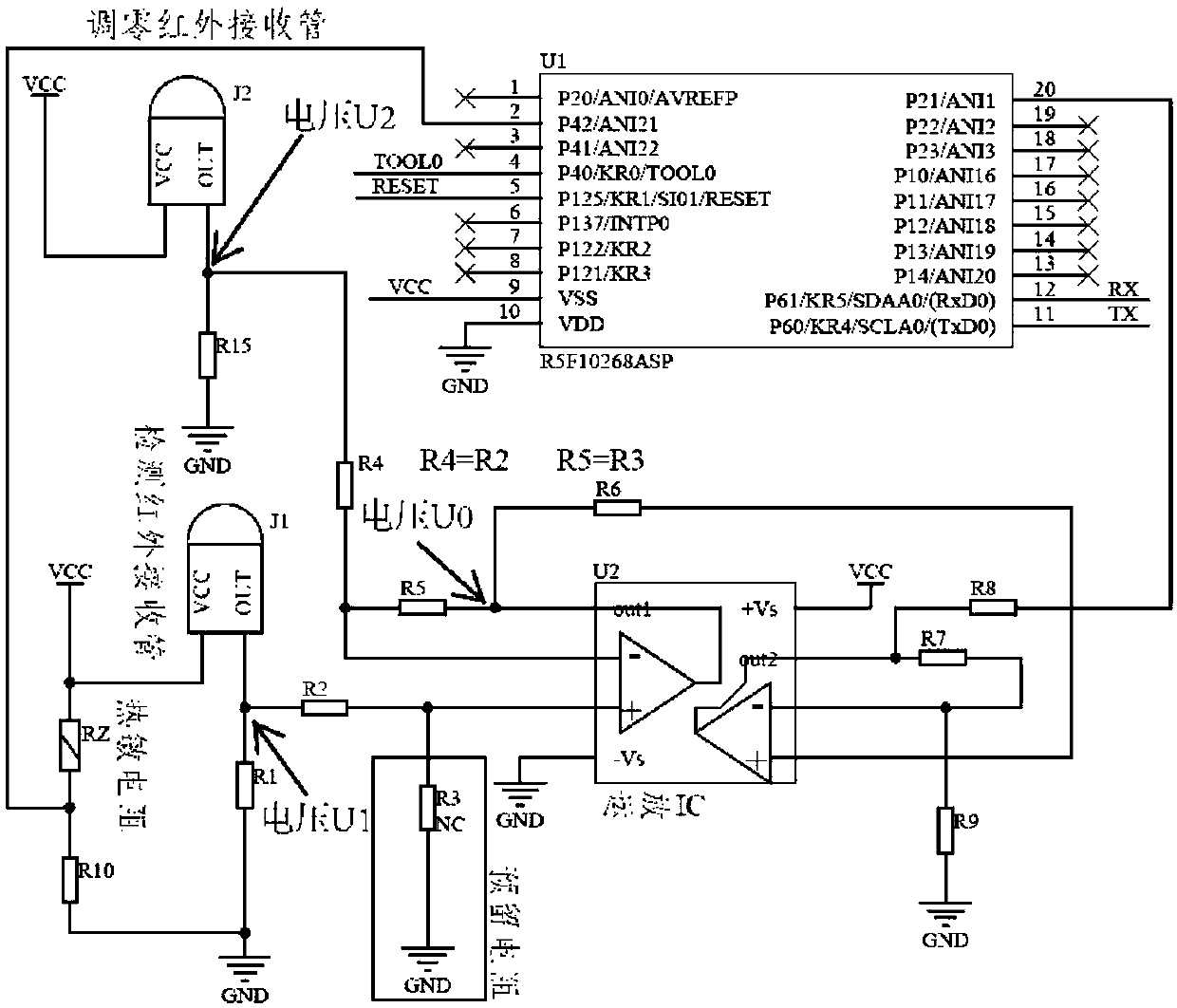
[0065] Embodiment 1 provides a sensor circuit applied to a smoke machine, such as image 3 As shown, it includes a zero-adjusting infrared receiving tube J2, a fourth resistor R4, a fifteenth resistor R15, a detecting infrared receiving tube J1, a second resistor R2, a first resistor R1, a secondary differential amplifier circuit, and a sixth resistor R6 , fifth resistor R5, third resistor R3, seventh resistor R7, ninth resistor R9, eighth resistor R8, thermistor RZ, tenth resistor R10, chip U1, programming module, serial communication module CN2, tenth Three resistors R13, fourteenth resistor R14, first capacitor C1, second capacitor C2;

[0066] One end of the zero-adjusting infrared receiving tube J2 is connected to the power supply, one of the other ends is connected to the secondary differential amplifier circuit through the fourth resistor R4, and the other is grounded through the fifteenth resistor R15;

[0067] One end of the detection infrared receiving tube J1 is co...

Embodiment 2

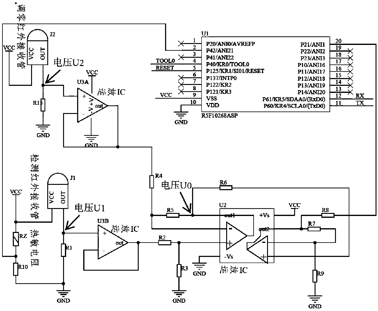
[0080] Embodiment 2 provides a sensor circuit applied to a smoke machine, such as Figure 4 As shown, it includes a zero-adjusting infrared receiving tube J2, a fourth resistor R4, a fifteenth resistor R15, a detecting infrared receiving tube J1, a second resistor R2, a first resistor R1, a secondary differential amplifier circuit, and a sixth resistor R6 , the fifth resistor R5, the third resistor R3, the seventh resistor R7, the ninth resistor R9, the eighth resistor R8, the voltage follower U3A, the voltage follower U3B, the thermistor RZ, the tenth resistor R10, the chip U1, the burner Recording module, serial port communication module CN2, thirteenth resistor R13, fourteenth resistor R14, first capacitor C1, second capacitor C2;

[0081] One end of the zero-adjusting infrared receiving tube J2 is connected to the power supply, one of the other ends is connected to the secondary differential amplifier circuit through the voltage follower U3A and the fourth resistor R4, and...

Embodiment 3

[0095] Embodiment 1 provides a sensor circuit applied to a smoke machine, such as Figure 5 As shown, it includes a zero-adjusting infrared receiving tube J2, a fourth resistor R4, a fifteenth resistor R15, a detection infrared receiving tube J1, a second resistor R2, a first resistor R1, a secondary conventional amplifier circuit, a differential amplifier circuit, Fourth resistor R4, third resistor R3, sixth resistor R6, fifth resistor R5, eighth resistor R8, thermistor RZ, tenth resistor R10, chip U1, programming module, serial port communication module CN2, thirteenth resistor Resistor R13, fourteenth resistor R14, first capacitor C1, second capacitor C2;

[0096] One end of the zero-adjusting infrared receiving tube J2 is connected to the power supply, one of the other ends is connected to the secondary differential amplifier circuit through the fourth resistor R4, and the other is grounded through the fifteenth resistor R15;

[0097] One end of the detection infrared rec...


PUM


Abstract

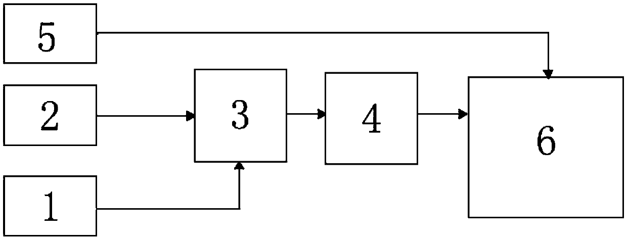
The invention discloses a sensor circuit applied on a range hood. The sensor circuit comprises a zero setting infrared reception module, a detection infrared reception module, a differential amplification module, an A / D acquisition module, a processor and a temperature acquisition module, wherein both the zero setting infrared reception module and the detection infrared reception module are connected with the processor through the differential amplification module and the A / D acquisition module in sequence; the processor is also connected with the temperature acquisition module; the temperature acquisition module is arranged in the vicinity of the detection infrared reception module and is used for acquiring the environment temperature of the detection infrared reception module; the performance of the zero setting infrared reception module and the detection infrared reception module is similar or same; and the differential amplification module comprises a differential amplification circuit and is used for counteracting the electric signal changes, generated by the environment, received by the zero setting infrared reception module and the detection infrared reception module. The sensor circuit is realizing the automatic zero setting of the circuit when the environment light or temperature changes, thereby reducing the deviation of the signals output by the circuit and correctlyreflecting the detection concentration.

Description

technical field [0001] The invention belongs to the technical field of smoke machine control circuits, and in particular relates to a sensor circuit applied to a smoke machine and the smoke machine. Background technique [0002] The traditional zeroing circuit is usually fixed zeroing, which is not enough for the infrared receiving tube affected by ambient light and ambient temperature. Different ambient light and ambient temperature will affect the output current of the infrared receiving tube, so that the fixed zeroing The method is meaningless; when the infrared receiving tube is affected by ambient light and ambient temperature, the detection range of the infrared receiving tube for the concentration of oil fume will be reduced, so that it cannot reach the proper detection range, thereby affecting the detection effect. Contents of the invention [0003] In view of this, the main purpose of the present invention is to provide a sensor circuit applied to a cigarette mach...

Claims


Application Information

Patent Timeline
Patent Type & Authority Applications(China)
IPC IPC(8): G01N15/06H03F3/68H03F3/45
CPCG01N15/06H03F3/68H03F3/45G01N15/075
Inventor 郭文光闫旺刘明雄潘叶江
Owner VATTI CORP LTD
Learn More