

Large-axis peristaltic detection method applicable to power station unit
A technology for power station units and detection methods, which is applied in the direction of motor generator testing, the use of electrical devices, and the use of electromagnetic means, can solve problems such as hidden dangers in the operation of bearing bushes, and achieve the effect of advanced algorithms
- Summary
- Abstract
- Description
- Claims
- Application Information
AI Technical Summary
Problems solved by technology
Method used
Image

Examples
Embodiment
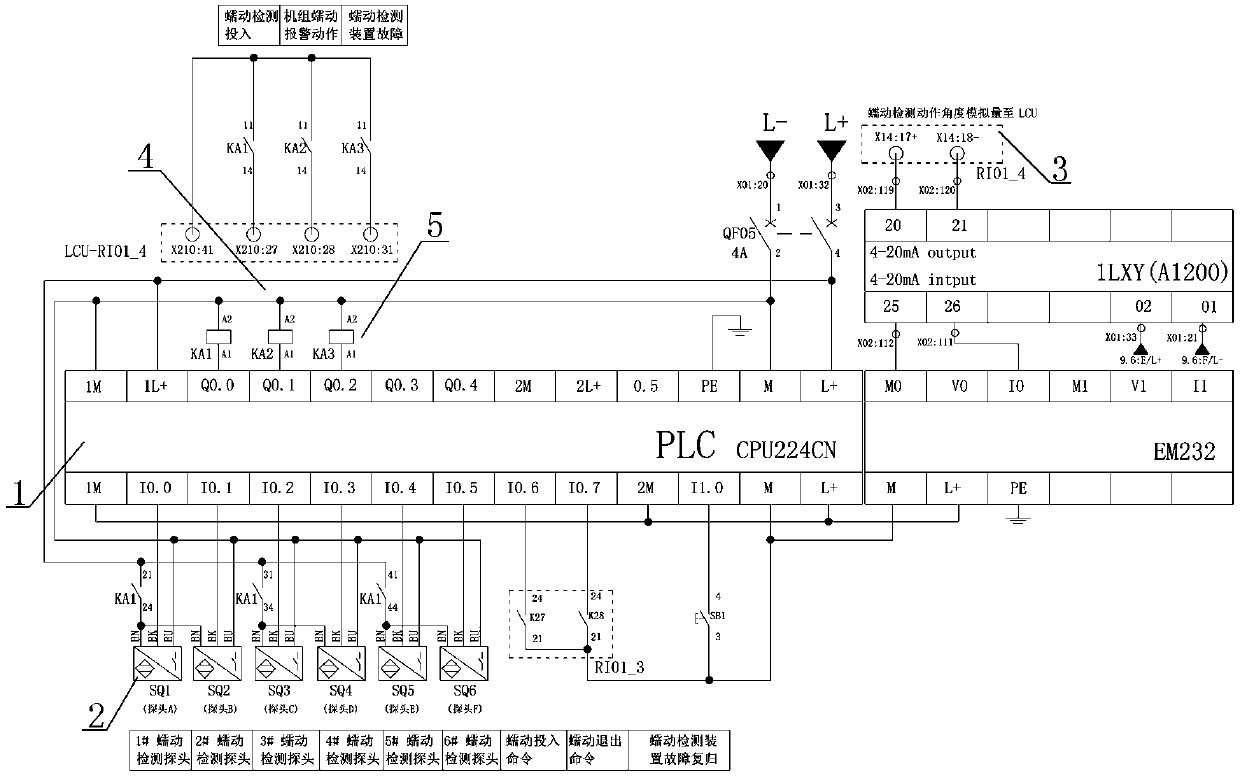
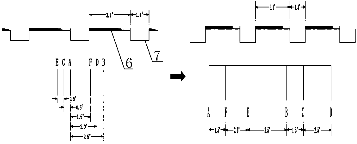
[0046] like Figures 1 to 3 As shown, the number of speed-measuring toothed belts and empty slots of the large shaft of the Harbin Electric Group on the right bank of the Three Gorges are 80, the length of a single toothed belt: 50mm, the length of a single empty slot: 110mm, and the duty cycle is 0.31. The angle value of the center of the major axis corresponding to the arc length of a toothed belt plus the arc length of an empty slot:
[0047] φ=360° / 80=4.5°.
[0048] The angle value of the large axis center angle corresponding to the arc length of a single toothed disc: 4.5°*50 / 160=1.4°.
[0049] The angle value of the large axis center angle corresponding to the arc length of a single empty slot:
[0050] 4.5°*110 / 160=3.1°.
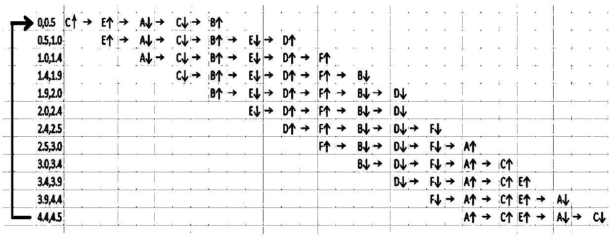
[0051] After analysis and calculation, six probes must be installed, and the distance between each probe is a multiple of 0.5°, so as to meet the national standard creep requirements. The identifiable domain of one cycle of the gear plate is 0.5*2=1...
PUM
 Abstract
Description
Claims
Application Information