Supercharge Your Innovation With Domain-Expert AI Agents!

Vibration separation beneficiation equipment

A technology of mineral processing equipment and vibration separation, applied in the field of mineral processing, can solve the problems of small processing capacity, low recovery rate of useful minerals, large water consumption, etc., and achieve the effects of large processing capacity, improved recovery rate, and high recovery rate of useful minerals.

Pending Publication Date: 2019-09-10
四川省摘塬勇鑫矿业科技有限公司
View PDF0 Cites 1 Cited by
  • Summary
  • Abstract
  • Description
  • Claims
  • Application Information

AI Technical Summary

Problems solved by technology

[0002] At present, the shaker is the main equipment for gravity separation of useful minerals and gangue minerals. When the shaker is washing useful minerals with a high grade, the recovery rate is not bad, and it can also produce economic benefits. However, with the collapse of resources, , the selected grade of useful minerals is getting lower and lower, and the grinding is getting finer and finer. The shaking table reveals its shortcomings: the recovery rate of useful minerals is low, and the comprehensive recovery and utilization of tailings is even weaker.
[0003] The shaking table covers a large area, and has a small processing capacity and a large water consumption. The telescopic movement during the shaking table operation will cause the minerals to move back and forth. The fine-grained useful minerals and inclusions are easy to flow away with the gangue minerals and water, and the useful minerals are recovered. low rate

Method used


Image

  • Vibration separation beneficiation equipment
  • Vibration separation beneficiation equipment
  • Vibration separation beneficiation equipment

Examples


Embodiment Construction

[0021] The embodiments of the present invention are described in further detail below in conjunction with the accompanying drawings, but the present embodiments are not intended to limit the present invention. All similar structures and similar changes of the present invention should be included in the scope of protection of the present invention. The commas in all represent the relationship between and, and the English letters in the present invention are case-sensitive.

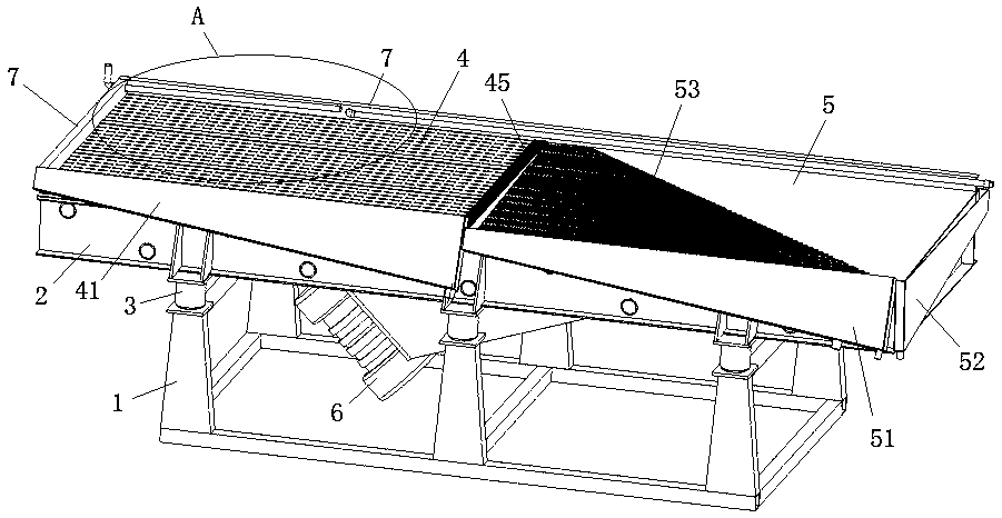
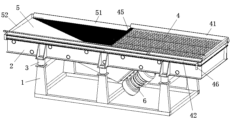
[0022] Such as Figure 1-3 As shown, a vibration separation mineral processing equipment provided by the first embodiment of the present invention includes a machine base 1 and a mineral processing bed, and is characterized in that: the machine base 1 is provided with a vibrating frame 2 and a plurality of exciting springs 3;

[0023] Each excitation spring 3 is divided into two groups, and each group includes at least two excitation springs, one group of excitation springs is arranged on the left part of t...


PUM


Abstract

The invention provides vibration separation beneficiation equipment and relates to the field of beneficiation technology. The vibration separation beneficiation equipment solves the technical problemof increasing the recovery rate of useful minerals. The equipment comprises a base and a beneficiation bed. A vibrating frame and a plurality of excitation springs are arranged on the base. A vibrating motor for driving linear vibration of the vibrating frame is arranged on the vibrating frame. The beneficiation bed is fixed on the vibrating frame, water blocking plates are fixed on the front edgeand the left edge of the beneficiation bed, and a feeding pipe and a flushing pipe are arranged at the left edge portion of the beneficiation bed. An enrichment plate is fixed on the beneficiation bed, the enrichment plate is inclined downward from left to right, and a plurality of sand selection grooves are formed in the enrichment plate. The sand selection grooves are sequentially formed in parallel from left to right. The lengths of all the sand selection grooves increase from left to right, a coarse sand material enrichment tank is arranged at the rear edge portion of the enrichment plate, and a tail material collection tank is arranged at the right edge portion of the enrichment plate. The equipment is particularly suitable for the re-election of tailings, tails and slag.

Description

technical field [0001] The invention relates to mineral processing technology, in particular to a technology of vibration separation mineral processing equipment. Background technique [0002] At present, the shaker is the main equipment for gravity separation of useful minerals and gangue minerals. When the shaker is washing useful minerals with a high grade, the recovery rate is not bad, and it can also produce economic benefits. However, with the collapse of resources, , the selected grade of useful minerals is getting lower and lower, and the grinding is getting finer and finer. The shaking table reveals its shortcomings: the recovery rate of useful minerals is low, and the comprehensive recovery and utilization of tailings is even more powerless. [0003] The shaking table covers a large area, and has a small processing capacity and a large water consumption. The telescopic movement during the shaking table operation will cause the minerals to move back and forth. The f...

Claims


Application Information

Patent Timeline
IPC IPC(8): B03B5/02B03B11/00
CPCB03B5/02B03B11/00
Inventor 蒋天勇
Owner 四川省摘塬勇鑫矿业科技有限公司
Features
  • R&D
  • Intellectual Property
  • Life Sciences
  • Materials
  • Tech Scout
  • Unparalleled Data Quality
  • Higher Quality Content
  • 60% Fewer Hallucinations
Learn More