
Tool changing device and method for numerical control machine tool

A technology of CNC machine tools and tool changing devices, applied in positioning devices, metal processing mechanical parts, clamping and other directions, can solve problems such as poor tool changing efficiency, save time for tool loosening, good stability, and improve tool changing. the effect of speed

Inactive Publication Date: 2019-09-10
TAIZHOU YIKONG AUTOMATION EQUIP
View PDF12 Cites 6 Cited by
  • Summary
  • Abstract
  • Description
  • Claims
  • Application Information

AI Technical Summary

Problems solved by technology

Although the tool changing device for horizontal machining centers can change the tool, the tool changing device for horizontal machining centers performs tool changing step by step, and only after one step is completed In the next step, the tool change efficiency is not good

Method used


Image

  • Tool changing device and method for numerical control machine tool
  • Tool changing device and method for numerical control machine tool
  • Tool changing device and method for numerical control machine tool

Examples


Embodiment 1

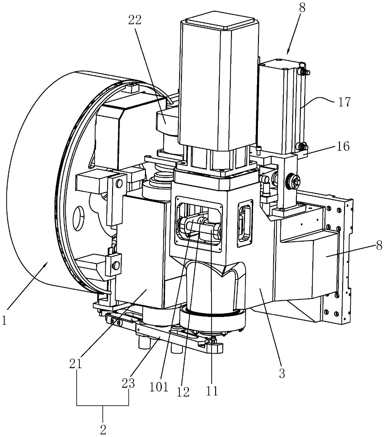
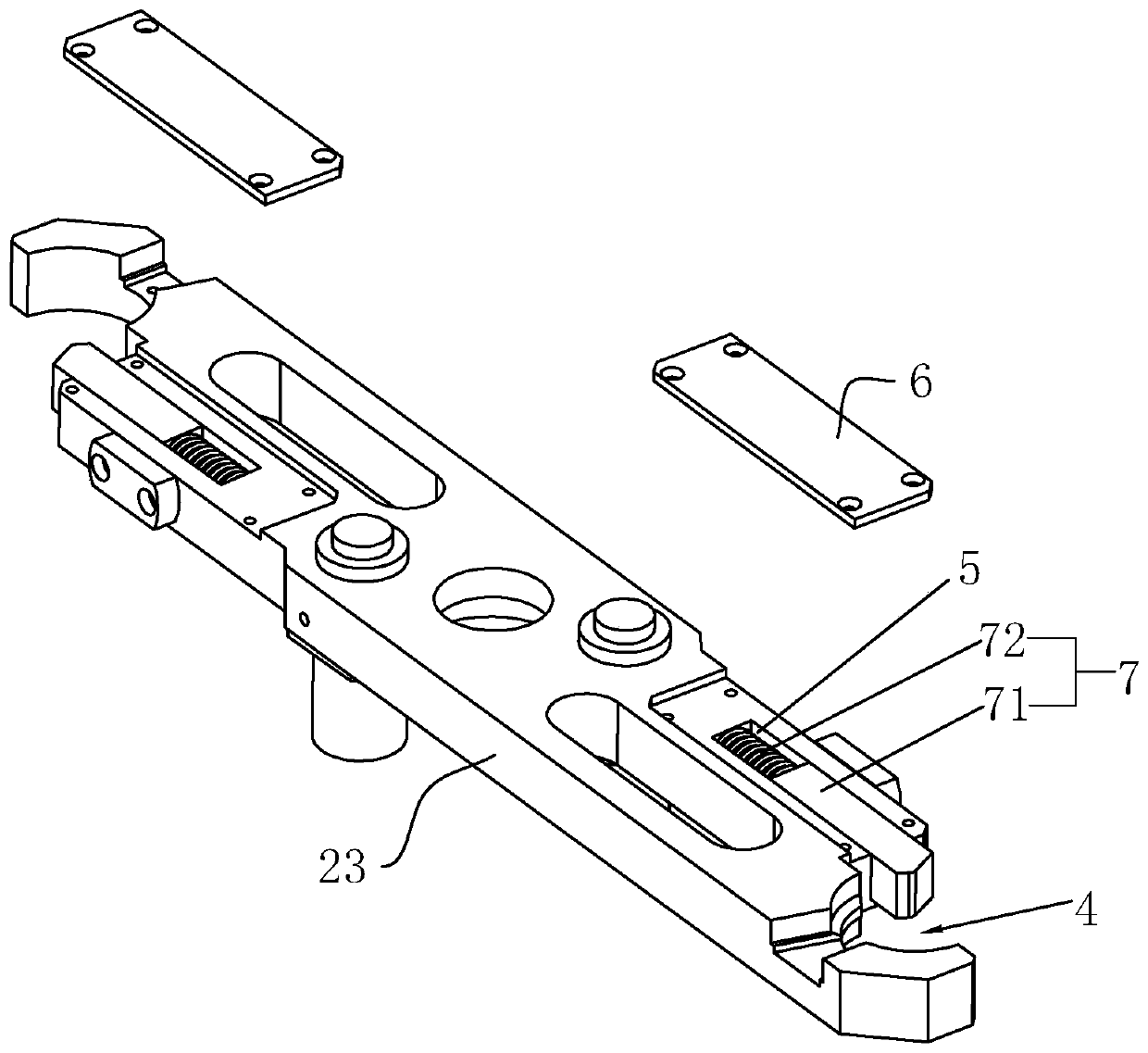
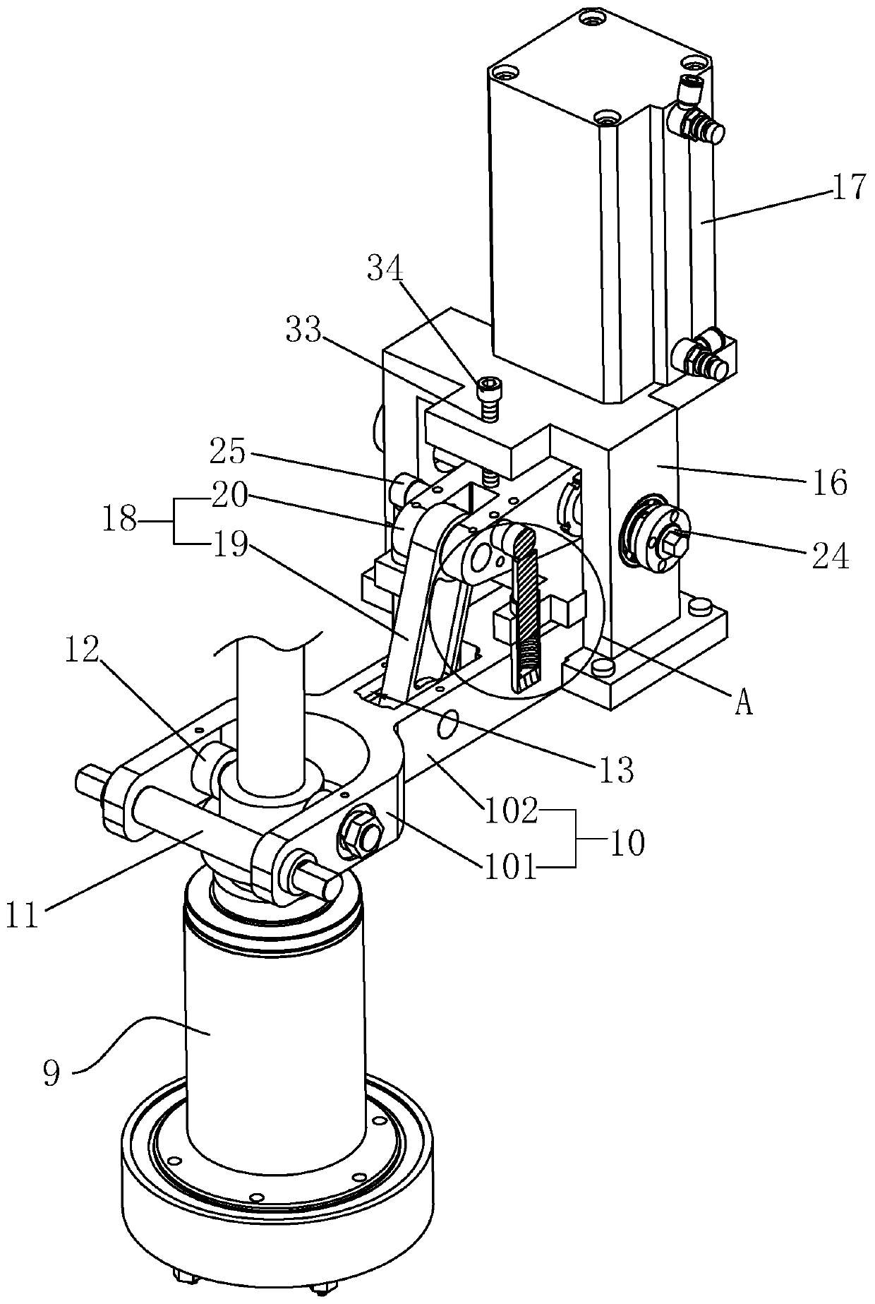
[0036] Such as figure 1 and 3As shown, a tool changing device for a CNC machine tool includes a tool magazine mechanism 1 , a spindle box 3 , and a tool changing mechanism 2 located between the tool magazine mechanism 1 and the spindle box 3 . The spindle box 3 is provided with a spindle 9 for clamping tools. For the specific structure of the spindle, refer to the Chinese patent with the notification number CN203266217U, including a gas-hydraulic pressurized cylinder, a spindle, a pressure rod, a disc spring, a pressure sleeve, a marble, and a gas cylinder. The hydraulic booster cylinder is located above the pressure rod, and the gas-hydraulic booster cylinder is used to press down the pressure rod. Used for clamping tools, the disc spring is sleeved on the pressure rod. The tools used by CNC machine tools usually include tool holders and pull studs. When the CNC machine tool equipped with the spindle tool release mechanism needs to release the tool, the worker presses the ...

Embodiment 2

[0048] A tool changing method for a numerically controlled machine tool. The tool changing method for a numerically controlled machine tool provided in this embodiment is applied to the tool changing device for a numerically controlled machine tool described in Embodiment 1. The specific steps of the tool changing method of the numerically controlled machine tool are as follows:

[0049] Preparation step: the tool changing arm 23 of the tool changing mechanism 2 is in the initial position to be ready;

[0050] Step of loosening the tool in advance: before the tool changing arm 23 of the tool changing mechanism 2 acquires the tool to be replaced on the main shaft 9, the piston rod of the servo drive device 17 pre-extends a part of the stroke to act on the floating end of the tool releasing arm 10, so that The tool release roller 12 forces the tool to be replaced clamped on the main shaft 9 to be in a state close to the tool release, that is, the tool is released in advance;

...


PUM


Abstract

The invention discloses a tool changing device and method for a numerical control machine tool. The device comprises a tool magazine mechanism, a main shaft box, a main shaft and a tool changing mechanism. The main shaft box is provided with a main shaft tool loosening mechanism used for releasing a tool at the lower end of the main shaft, the main shaft tool loosening mechanism comprises a tool loosening base and a tool loosening arm, the tool loosening base is fixedly installed on the main shaft box, the tool loosening arm is provided with a tool loosening roller used for pressing a pressingrod on the main shaft, the main shaft tool loosening mechanism further comprises a servo driving device, the servo driving device is arranged on the tool loosening base, the driving end of the servodriving device is vertically downward, one end of the tool loosening arm is rotationally connected to the main shaft box, the other end of the tool loosening arm is located under the driving end of the servo driving device, a connecting rod mechanism is arranged between the middle of the tool loosening arm and the tool loosening base, and the connecting rod mechanism is used for enabling the end,located below the servo driving device, of the tool loosening arm to be in a suspended mode. According to the key point of the technical scheme, the tool changing device of the numerical control machine tool improves tool changing efficiency in the way of loosening the tool in advance.

Description

technical field [0001] The invention relates to the technical field of numerical control machine tools, in particular to a tool changing device and a tool changing method of a numerical control machine tool. Background technique [0002] CNC machine tool is the abbreviation of numerical control machine tool, which is an automatic machine tool equipped with a numerical control system. The numerical control system can logically process the program specified by the control code or other symbolic instructions, decode it, express it in coded numbers, and input it into the numerical control device through the information carrier. After calculation and processing, various control signals are sent by the numerical control device to control the movement of the machine tool, and the parts are automatically processed according to the shape and size required by the drawing. [0003] The existing Chinese patent with publication number CN108098421A discloses a tool changing device for a ...

Claims


Application Information

Patent Timeline
Patent Type & Authority Applications(China)
IPC IPC(8): B23Q3/157
CPCB23Q3/15773
Inventor 周祥兵
Owner TAIZHOU YIKONG AUTOMATION EQUIP
Learn More