Digital controlled drill for machining PCBs (Printed Circuit Boards) and tool changing method of digital controlled drill

A CNC drilling machine, PCB board technology, applied in the direction of metal processing equipment, metal processing machinery parts, manufacturing tools, etc., can solve the problems of reduced drilling quality, large processing errors, slow tool change efficiency, etc., to improve tool change efficiency, The effect of reducing size error and ensuring accuracy

Pending Publication Date: 2019-07-26
珠海德景电子有限公司
View PDF0 Cites 4 Cited by
  • Summary
  • Abstract
  • Description
  • Claims
  • Application Information

AI Technical Summary

Problems solved by technology

[0002] With the development of electronic industry technology, the market has higher and higher requirements for the drilling quality of PCB boards. At present, the drills dedicated to drilling PCB boards have a short service life. In order to ensure the drilling quality, the drills are used continuously for a long time. The tool must be changed after the tool change, but most of the CNC machine tools on the market currently use manual tool change, the tool change efficiency is slow, it is difficult to set the tool after the tool change, resulting in large processing errors and reducing the quality of drilling

Method used


Image

  • Digital controlled drill for machining PCBs (Printed Circuit Boards) and tool changing method of digital controlled drill
  • Digital controlled drill for machining PCBs (Printed Circuit Boards) and tool changing method of digital controlled drill
  • Digital controlled drill for machining PCBs (Printed Circuit Boards) and tool changing method of digital controlled drill

Examples


Embodiment Construction

[0032] The idea, specific structure and technical effects of the present invention will be clearly and completely described below in conjunction with the embodiments and accompanying drawings, so as to fully understand the purpose, features and effects of the present invention. Apparently, the described embodiments are only some of the embodiments of the present invention, rather than all of them. Based on the embodiments of the present invention, other embodiments obtained by those skilled in the art without creative efforts belong to The protection scope of the present invention.

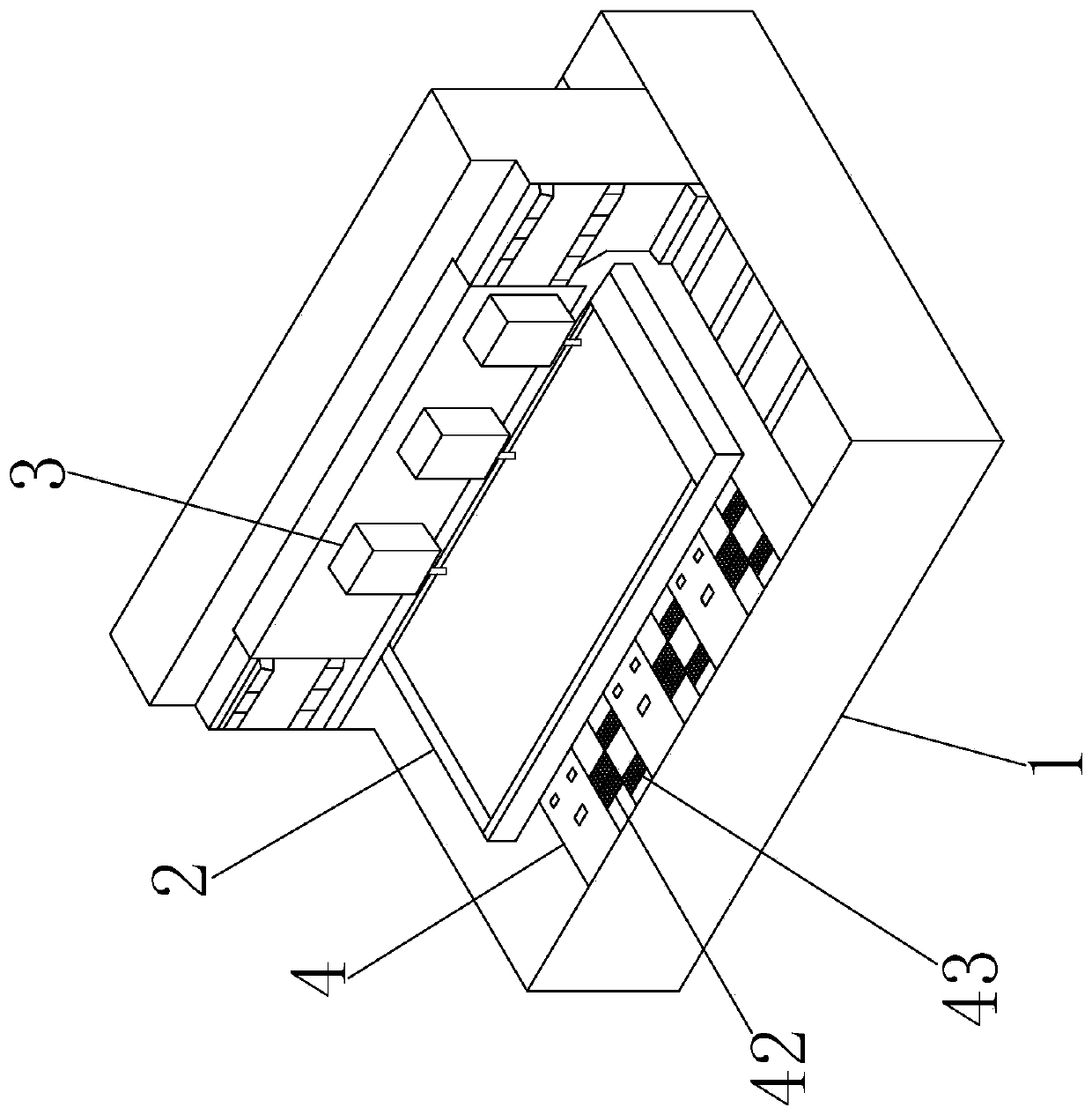
[0033] Such as figure 1 A kind of CNC drilling machine shown for processing PCB boards includes a base 1, a workbench 2 that can be moved on the base 1, a drill assembly 3 that can move relative to the workbench 2, and a drill assembly 3 that is arranged on the workbench 2- Side tool changer assembly 4.

[0034] The workbench 2 and the drill bit assembly 3 are respectively connected with a two-a...


PUM


Abstract

The invention relates to the technical field of PCB machining, in particular to a digital controlled drill for machining PCBs (Printed Circuit Boards) and a tool changing method of the digital controlled drill. The digital controlled drill comprises a base, a workbench, a drill bit assembly and a tool changing assembly, wherein the workbench is movably arranged on the base; the drill bit assemblycan move relative to the workbench; and the tool changing assembly is arranged on one side of the workbench. According to the digital controlled drill disclosed by the invention, one side of a tool apron is provided with a clamping assembly for transferring a drilling tool, the clamping assembly can transfer a new drilling tool from a new tool magazine to one of tool holders along with the tool apron, a drilling tool to be replaced on the tool apron is placed on the other tool holder, and the clamping assembly transfers the replaced drilling tool into a used tool magazine after the tool apronclamps the new drilling tool, so that automatic tool changing is realized; manual operation is not required; and the tool changing efficiency is improved. According to the tool changing method disclosed by the invention, a tool setting operation is performed before and after tool changing, so that the relative position accuracy of the drilling tool relative to the tool apron and / or the workbench is ensured; size error after replacement of the drilling tool is reduced; and the drilling accuracy is improved.

Description

technical field [0001] The invention relates to the technical field of PCB board processing, in particular to a numerical control drilling machine used for processing PCB boards and a tool changing method of the numerical control drilling machine. Background technique [0002] With the development of electronic industry technology, the market has higher and higher requirements for the drilling quality of PCB boards. At present, the drills dedicated to drilling PCB boards have a short service life. In order to ensure the drilling quality, the drills are used continuously for a long time. Afterwards, the tool must be changed, but most of the CNC machine tools on the market currently use manual tool change, the tool change efficiency is slow, and it is difficult to set the tool after the tool change, resulting in large processing errors and reducing the quality of drilling. Contents of the invention [0003] In order to overcome the above-mentioned deficiencies in the prior a...

Claims


Application Information

Patent Timeline
Patent Type & Authority Applications(China)
IPC IPC(8): H05K3/00B23Q3/157
CPCB23Q3/157B23Q3/15773H05K3/00H05K3/0047
Inventor 杨书弟
Owner 珠海德景电子有限公司
Why Eureka
Try Eureka