

Automatic extension cutter frame device for numerical control machine
An automatic retractable and telescopic device technology, applied in the field of numerical control, can solve the problems affecting the efficiency of numerical control machining and low tool change efficiency, and achieve the effect of improving tool change efficiency and work efficiency
- Summary
- Abstract
- Description
- Claims
- Application Information
AI Technical Summary
Problems solved by technology
Method used
Image

Examples
Embodiment 1
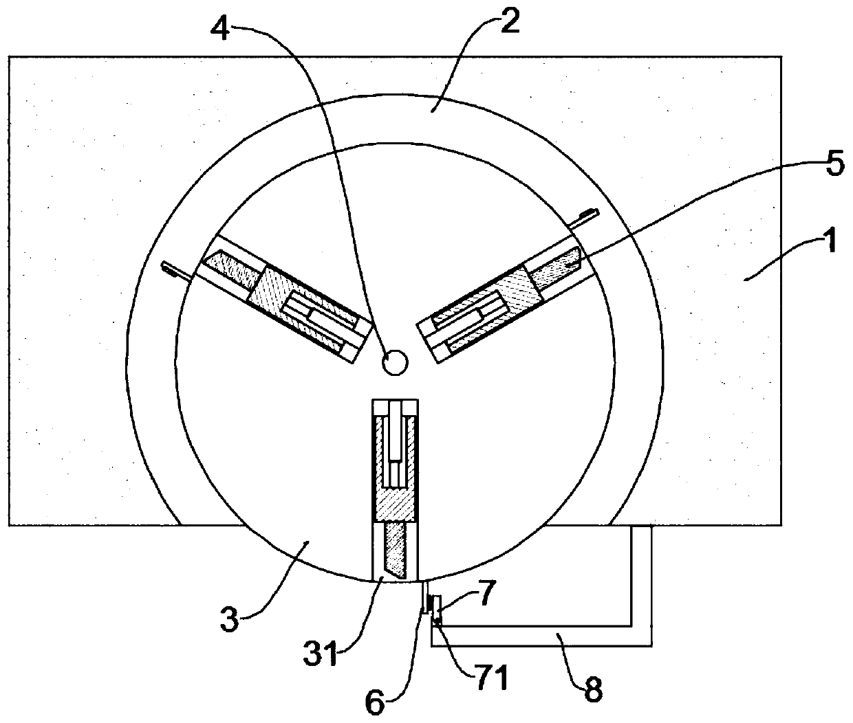
[0029] see Figure 1~3 , in the embodiment of the present invention, the drive assembly includes a first magnetic block group 23 and a second magnetic block group 26, and the first magnetic block group 23 consists of two electromagnetic blocks fixed to the chute 31 and the tool holder 51 respectively Composition, one end of the knife rest 51 close to the center of the turntable 3 is elastically connected to the chute 31 through the first elastic member 22; the two sides of the end of the knife rest 51 far away from the center of the turntable 3 are symmetrically provided with installation grooves 512, and sliding cards in the installation grooves 512 A locking block 24 is provided, and the locking block 24 is elastically connected to the installation groove 512 through the second elastic member 25, and a locking block 311 matching with the locking block 24 is provided in the chute 31; the second magnetic block group 26 is composed of two The electromagnetic blocks respectively...
Embodiment 2
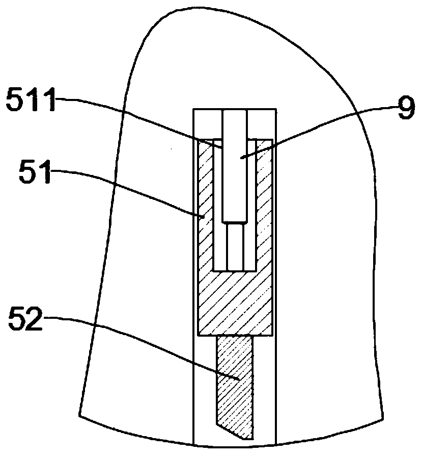
[0034] see Figure 4~6 , in the embodiment of the present invention, the drive assembly includes a telescopic device 9, the fixed end of the telescopic device 9 is fixed in the chute 31, the movable end of the telescopic device 9 is connected to the tool holder 51, and the telescopic device 9 is electrically connected to the trigger assembly.
[0035] In this embodiment, when the sensor 6 rotates to a position that matches the trigger 7, the retractable device 9 drives the tool holder 51 to move outward, and then drives the cutter head 52 to extend out of the chute 31. When the sensor 6 rotates to the position that matches the trigger When the part 7 is matched with the position, the extension device 9 drives the knife rest 51 to move inward, and then drives the knife head 52 to retract into the chute 31 .
[0036] The specific structure of the telescopic device 9 is not limited, and may be an electric telescopic rod, a pneumatic telescopic rod or a hydraulic telescopic rod. I...
PUM
 Abstract
Description
Claims
Application Information