
Gas roller for thin film traction

A technology of thin film and air roller, which is applied in the direction of thin material processing, coiling, transportation and packaging, etc. It can solve the problems of uneven air outlet from air holes, affecting the transmission and quality of thin-walled tubes, and achieves uniform air output and improved Production quality, friction reduction effect

Active Publication Date: 2019-09-10
CHONGQING RUITING PLASTIC
View PDF8 Cites 1 Cited by
  • Summary
  • Abstract
  • Description
  • Claims
  • Application Information

AI Technical Summary

Problems solved by technology

[0005] The purpose of the present invention is to provide an air roller for film traction to solve the problem in the prior art that the air roller device affects the transmission and quality of thin-walled tubes due to uneven air outlet from the air hole

Method used


Image

  • Gas roller for thin film traction
  • Gas roller for thin film traction
  • Gas roller for thin film traction

Examples


Embodiment 1

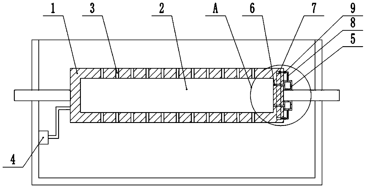
[0027] Embodiment one is basically as attached Figure 1 to Figure 4 Shown:

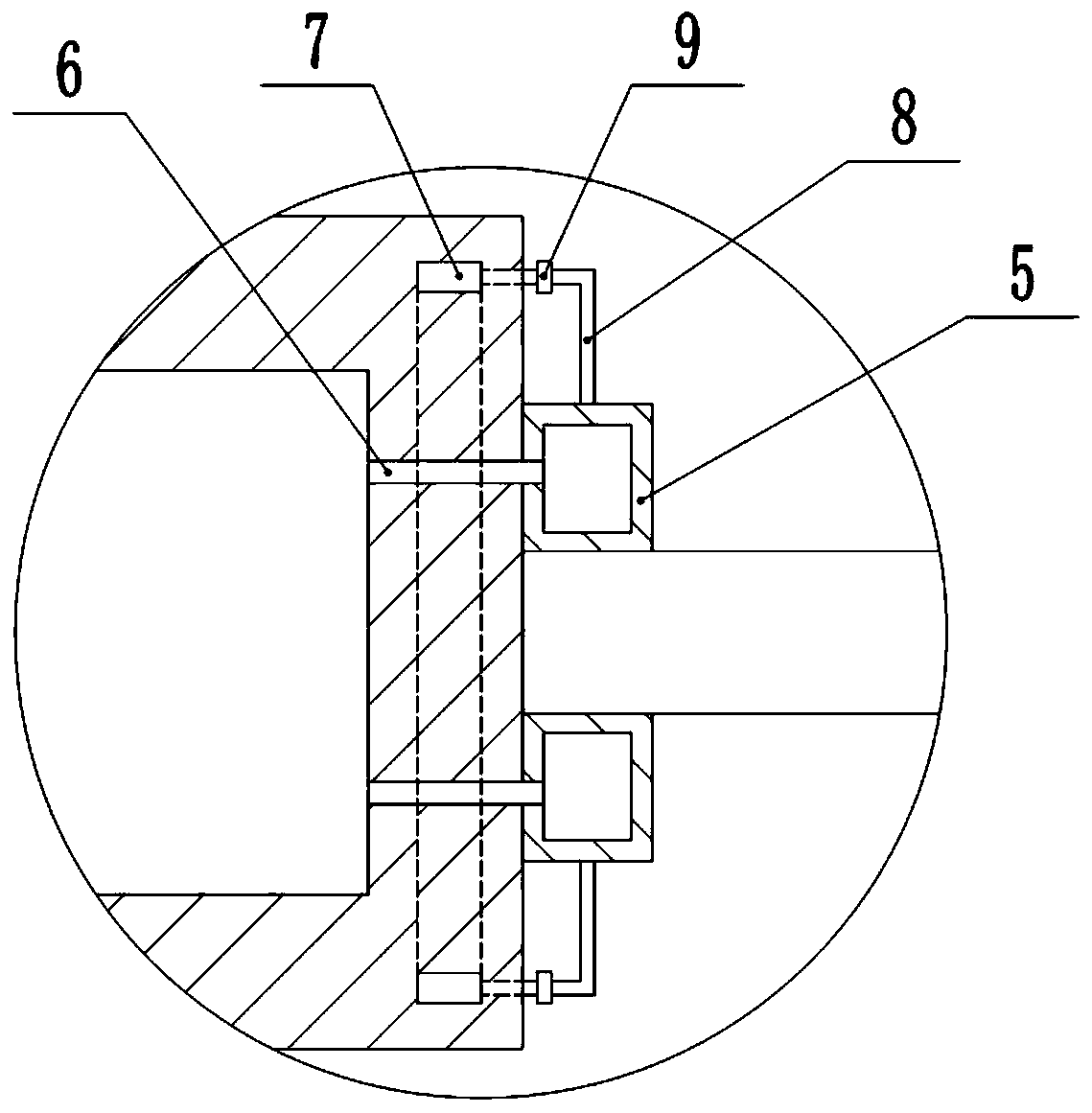
[0028] The air roller for film traction includes a roller body 1 with a cavity 2 in the roller body 1, and an air hole 3 connecting the cavity 2 with the outside world on the roller body 1. The left end of the roller body 1 is connected with a gas supply to the cavity 2. The air supply mechanism, in the present embodiment, the air supply mechanism is blower 4. The right end of the roller body 1 is provided with an air replenishing mechanism, which includes a cavity 5 fixed on the roller body 1, and the right end of the roller body 1 is provided with a drainage hole 6 communicating with the cavity 5, and the diameter of the drainage hole 6 is smaller than The diameter of the air holes 3 and the drainage holes 6 are evenly distributed in the circumferential direction on the roller body 1 . There is an annular cavity 7 inside the roller body 1, and a conduit 8 is connected between the annular cavity 7...

Embodiment 2

[0030] Embodiment two is basically as attached Figure 5 Shown:

[0031] The difference between this embodiment and Embodiment 1 is that it also includes a driving mechanism for driving the roller body 1 to reciprocate along the length direction of the roller body 1. The driving mechanism includes piston cylinders 11 arranged at both ends of the roller body 1. A piston 12 is slidingly connected, and a piston rod 13 is fixedly connected to the piston 12. The end of the piston rod 13 away from the piston cylinder 11 is coaxially fixedly connected with the roller body 1. The piston cylinder 11 is provided with an air inlet 3, and the piston cylinder 11 is also provided with A pressure valve 15 is installed, and an inflation mechanism is connected to the air inlet 3 . The inflation mechanism includes an air duct 16 communicated with the air inlet 3, and the air duct 16 is equipped with a valve 17 and a one-way valve 18 leading to the piston cylinder 11, and the air duct 16 at bot...


PUM


Abstract

The invention relates to the technical field of thin film machining, and discloses a gas roller for thin film traction. The gas roller comprises a roller body, a cavity is formed in the roller body, agas hole for communicating the cavity with the exterior is formed in the roller body, one end of the roller body is connected with a gas supply mechanism for supplying gas to the cavity, the other end of the roller body is provided with a gas supplementing mechanism, the gas supplementing mechanism comprises a cavity fixed to the roller body, the other end of the roller body is provided with a drainage hole for communicating with the cavity, an annular cavity is formed in the roller body, a guide pipe communicates between the annular cavity and the cavity, and a gas supplementing hole for communicating with the annular cavity is formed in the roller body. The problem that in the prior art, due to uneven outlet gas of the gas hole, the thin-wall pipe transmission and quality are affected is solved.

Description

technical field [0001] The invention relates to the technical field of film processing, in particular to an air roller for film traction. Background technique [0002] When the blow molding equipment is producing a film, the plastic raw material is extruded through the die to form a thin-walled tube, and the thin-walled tube is pulled upwards, and is pressed into a double-layer flat film through a herringbone plate and a pulling device, and then passed through a guide roller Transmission, and finally through the winding device for winding. During the transmission process of the thin-walled tube, due to the contact with the guide roller, a large friction force is likely to be generated between the two, and this friction force is likely to cause the thin-walled tube to wrinkle, or even cause the thin-walled tube to be pulled and ruptured. . [0003] In order to solve the above problems, an air roller device has appeared in the prior art. The device includes an air roller, an...

Claims


Application Information

Patent Timeline
IPC IPC(8): B65H20/02B65H27/00
CPCB65H20/02B65H27/00B65H2701/1133B65H2701/1752
Inventor 曹玉毛潞
Owner CHONGQING RUITING PLASTIC
Learn More