Buckling constrained beam and column self-reset joint based on steel-shape memory alloy (SMA) plate set element and assembly method

A buckling restraint and self-resetting technology, applied to building components, building types, buildings, etc., can solve the problems of increasing energy consumption capacity and complex design, and achieve the effects of improving energy consumption capacity, simple and convenient installation, and recoverable deformation

Pending Publication Date: 2019-09-10
CHONGQING UNIV +1
View PDF0 Cites 14 Cited by
  • Summary
  • Abstract
  • Description
  • Claims
  • Application Information

AI Technical Summary

Problems solved by technology

This joint solves the defect that the energy dissipation performance and self-resetting performance of the existing joints are difficult to have at the same time, and also overcomes the prestressing requirements of the post-tensioned joints and the complicated design of SMA bolt joints. proposed a combined connection method of T-shaped steel plate and SMA bone-shaped connecting plate. The T-shaped steel plate and beam flange realized the buckling constraint on the SMA bone-shaped connecting plate; The relative movement between the SMA bone-shaped ...

Method used


Image

  • Buckling constrained beam and column self-reset joint based on steel-shape memory alloy (SMA) plate set element and assembly method
  • Buckling constrained beam and column self-reset joint based on steel-shape memory alloy (SMA) plate set element and assembly method
  • Buckling constrained beam and column self-reset joint based on steel-shape memory alloy (SMA) plate set element and assembly method

Examples


Embodiment Construction

[0040] In order to make the technical problems, technical solutions and advantages to be solved by the present invention clearer, the following will describe in detail with reference to the accompanying drawings and specific implementation cases.

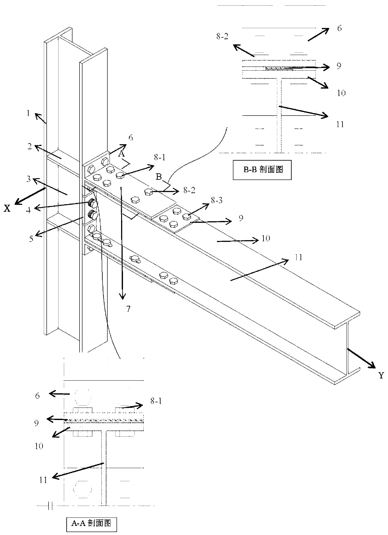
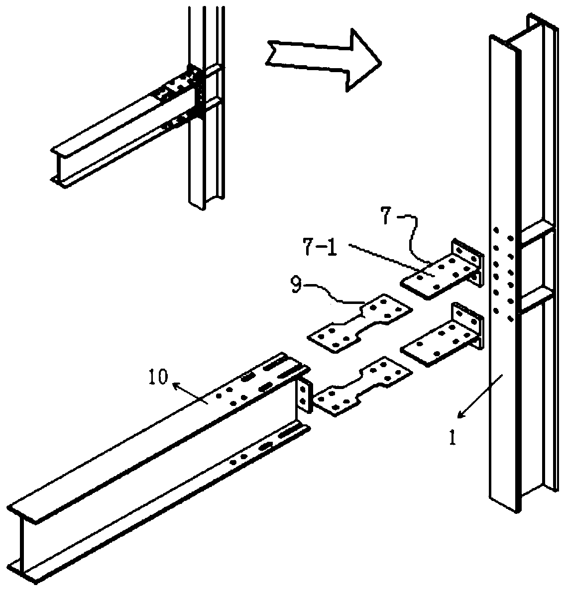
[0041] The present invention provides a buckling restrained beam-column self-resetting node based on steel-SMA plate group elements, including: 1. I-shaped steel column 2, I-shaped steel beam 3, T-shaped steel plate 4, SMA bone-shaped connecting plate 5, SMA Disc spring 6, rectangular end plate 7, column stiffener; friction type high-strength bolt.

[0042] This self-resetting node includes the selected beam-column connection node area in the structure, which includes I-shaped steel columns with stiffeners, I-shaped steel beams, T-shaped steel plates, SMA bone-shaped connecting plates, SMA disc springs, rectangular End plates and friction-type high-strength bolts. The three sides of the column stiffener are fillet-welded on the I-s...


PUM


Abstract

The invention discloses a buckling constrained beam and column self-reset joint based on a steel-shape memory alloy (SMA) plate set element and an assembly method. According to the buckling constrained beam and column self-reset joint based on the steel-SMA plate set element and the assembly method, a flange part adopts the combined connection of a T-shaped plate, an SMA bone-shaped connecting plate and a beam flange plate with U-shaped holes and long circular holes so as to realize the improvement of the force transmission performance of the joint; the U-shaped holes and the long circular holes are formed in a beam flange so as to realize the relative sliding of a beam and the SMA bone-shaped connecting plate, deformation is enabled to be mainly concentrated upon the SMA bone-shaped connecting plate, so that it is ensured that main components are in an elastic state; and meanwhile, the energy-dissipating capacity of the joint is improved through friction, so that the problem that theenergy-dissipating characteristic and the self-reset characteristic of an existing joint are difficult to combine at the same time is solved; and in addition, the combined connection can effectively solve the local buckling problem caused by the SMA bone-shaped connecting plate due to superelasticity. A rectangular end plate is welded to a beam web, SMA disk springs are further arranged, on the one hand, the energy-dissipating capacity of the joint is enhanced, on the other hand, the rotational deformation capacity of the joint is improved, and the good self-reset characteristic of the combined connection is better reflected.

Description

[0001] Technical field: [0002] The invention belongs to the field of structural engineering, and in particular relates to a buckling-constrained beam-column self-resetting node based on a steel-SMA plate group element and an assembly method thereof. [0003] Background technique: [0004] Steel structure is widely used in residential buildings, industrial plants and other places because of its advantages of light weight, high strength, good plastic toughness, uniform material, convenient construction and high comprehensive economic indicators. However, the survey of earthquake damage found that steel structure buildings are prone to large residual deformation due to excessive plastic deformation under earthquake action, which cannot meet the normal use requirements after the earthquake. Therefore, in order to reduce the residual deformation of the steel structure building, we must fully consider the strength, stiffness, stability, ductility and other mechanical properties of ...

Claims


Application Information

Patent Timeline
IPC IPC(8): E04B1/24E04B1/58E04B1/98E04H9/02
CPCE04B1/2403E04B2001/2406E04B2001/2415E04B2001/2418E04H9/021E04H9/024
Inventor 柯珂郭丽华周绪红任志浩王宇航张还阳何群
Owner CHONGQING UNIV
Why Eureka
Try Eureka