Efficient energy-consumption self-resetting anti-buckling support

An anti-buckling bracing and self-resetting technology, applied in earthquake resistance, building type, building, etc., can solve problems such as poor self-resetting bracing energy dissipation capacity

Pending Publication Date: 2019-09-10
SHANGHAI RES INST OF BUILDING SCI CO LTD +1
View PDF0 Cites 3 Cited by
  • Summary
  • Abstract
  • Description
  • Claims
  • Application Information

AI Technical Summary

Problems solved by technology

How to design a high-efficiency energy-consuming self-resetting anti-buckling support to solve the poor energy dissipation capacity of the self-resetting support has always been an engineering problem that is difficult to solve

Method used


Image

  • Efficient energy-consumption self-resetting anti-buckling support
  • Efficient energy-consumption self-resetting anti-buckling support
  • Efficient energy-consumption self-resetting anti-buckling support

Examples


Embodiment 1

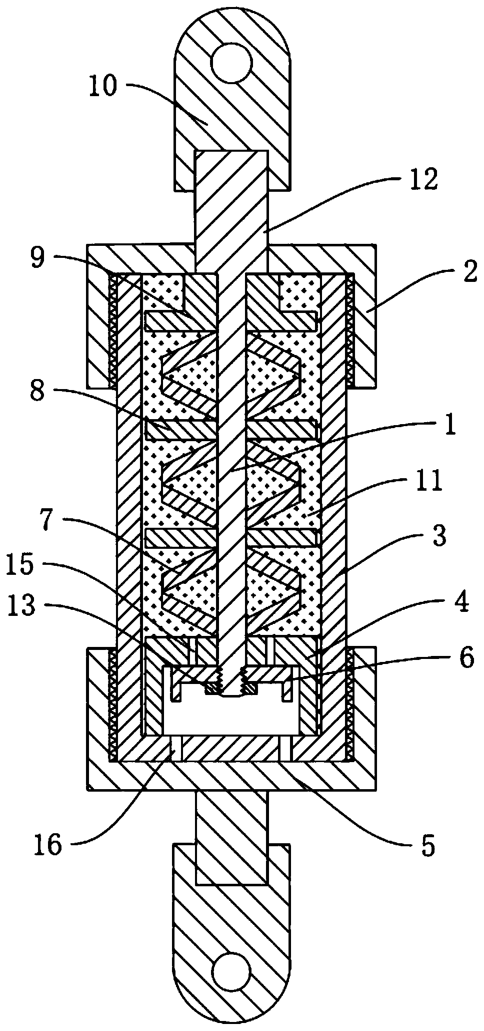
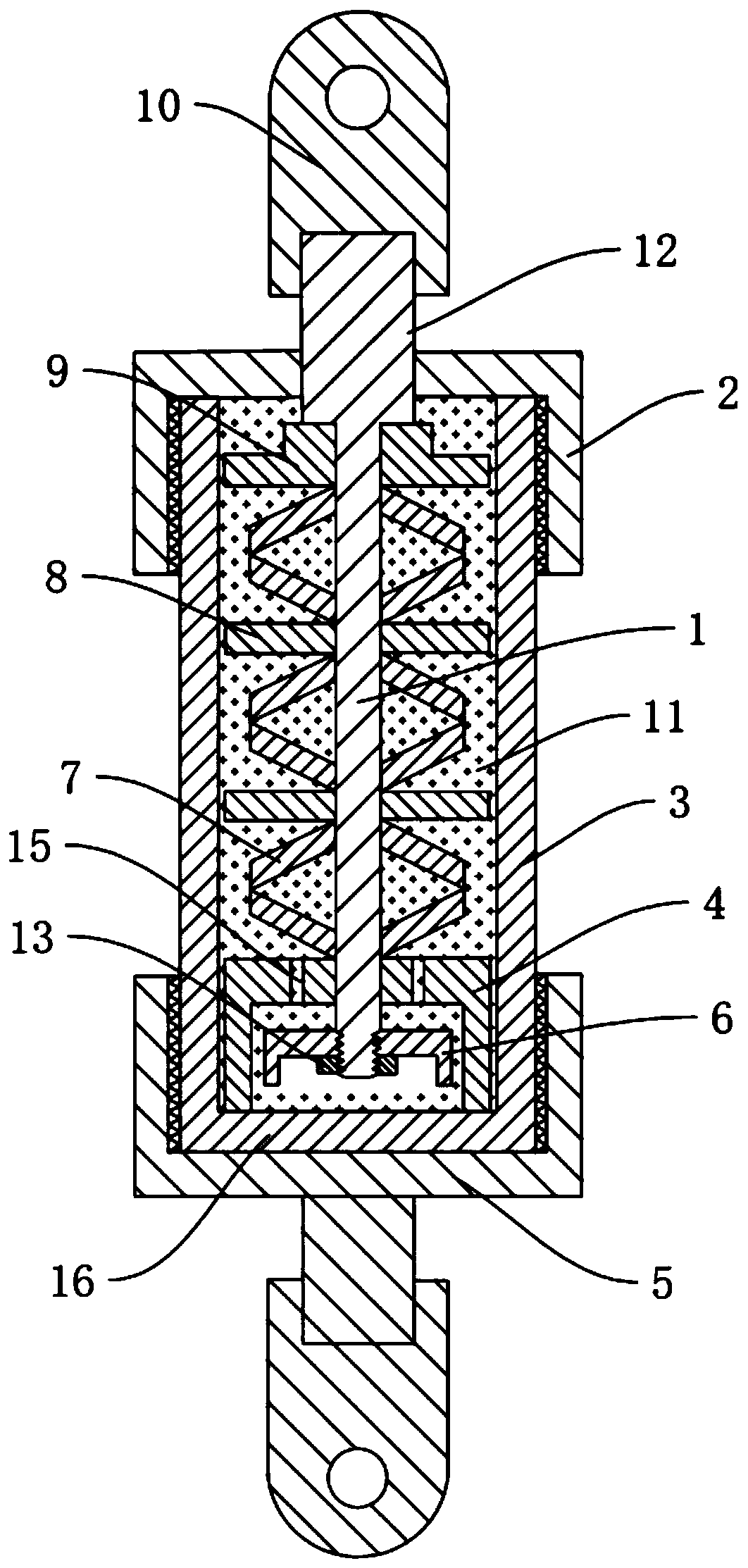
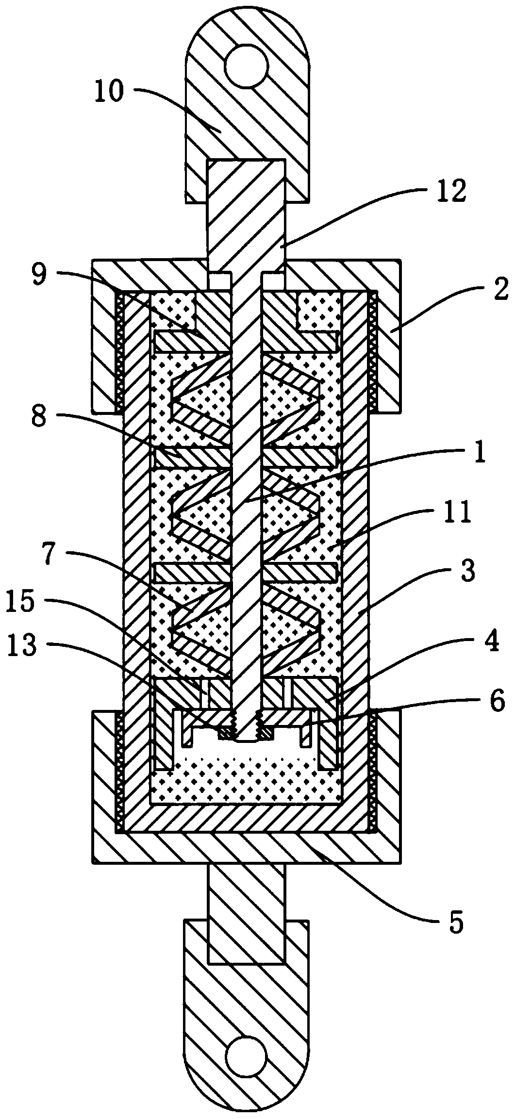
[0028] Embodiment 1: as Figure 1 to Figure 3 As shown, a high-efficiency energy-consuming self-resetting anti-buckling support proposed by the present invention includes a piston rod 1, an upper sealing cylinder 2, a sealing cylinder 3, and a lower sealing connector 5. The sealing cylinder 3 is filled with a damping material 11, The damping material 11 can be various types of damping materials such as viscous damping material and damping oil; the sealed cylinder body 3 can be a sealed integral type, a hole reserved at the bottom or a split type; the upper sealing cylinder 2 and the lower sealing connector 5 are separately arranged on Seal both ends of the cylinder body 3, the piston rod 1 is passed through the upper sealing cylinder 2; the upper connecting piece 10 is fixedly connected to the piston rod 1, and the upper connecting piece 10 and the lower sealing connecting piece 5 are respectively connected to the end of the piston rod 1 The bottom of the sealed cylinder 3 is ...

Embodiment 2

[0033] Embodiment 2, differs from Embodiment 1 in that: as Figure 4 As shown, the sealing energy-dissipating end plate 9 of the upper oil storage tank and the edges of the energy-dissipating partition 8 are all set as wide flange structures. The energy-dissipating end plate 9 sealed by the upper oil storage tank and the edge of the energy-dissipating partition 8 have a wide-wing structure, so that the shear area between the sealed cylinder 3 and the damping material 11 is significantly increased, and the internal parts of the component are relatively small to the damping material 11. The shearing and extrusion effects significantly improved the energy dissipation capacity of the support members.

Embodiment 3

[0034] Embodiment 3, differs from Embodiment 1 in that: as Figure 5 As shown, damping holes 14 for the circulation of damping material 11 are provided on the sealed energy-dissipating end plate 9 of the upper oil storage tank, the energy-dissipating partition 8 and the limiting energy-dissipating end cylinder 4 of the lower oil storage tank, and the sealed energy-consuming end of the upper oil storage tank The plate 9 , the energy-dissipating partition 8 and the limit energy-dissipating end cylinder 4 of the lower oil storage tank are attached to the inner wall of the sealed cylinder 3 or leave a gap with the sealed cylinder 3 . The damping hole 14 facilitates the circulation of the damping material 11 between the sealed energy-dissipating end plate 9 of the upper oil storage tank, the energy-dissipating partition 8 and the limiting energy-dissipating end cylinder 4 of the lower oil storage tank, which plays a damping role and improves the energy consumption of the supporting ...


PUM


Abstract

The invention discloses an efficient energy-consumption self-resetting anti-buckling support. The key points of the technical scheme are that the efficient energy-consumption self-resetting anti-buckling support includes a piston rod, an upper sealing cylinder, a sealing cylinder body and a lower sealing connection part; the piston rod penetrates through the upper sealing cylinder, the sealing cylinder body is filled with damping material, the piston rod sleeves a lower oil storage tank limiting energy-consumption end cylinder and an upper oil storage tank sealing energy-consumption end plate,the end, oriented towards the lower sealing connection part, of the piston rod is provided with a fixing energy-consumption end plate, the lateral wall, away from the lower sealing connection part, of the piston rod is provided with an extruding part which penetrates through the upper sealing cylinder and abuts against the upper oil storage tank sealing energy-consumption end plate, a damping reset mechanism is arranged between the upper oil storage tank sealing energy-consumption end plate and the lower oil storage tank limiting energy-consumption end cylinder. The efficient energy-consumption self-resetting anti-buckling support has a self- reset ability and stable and reliable efficient energy-consumption ability.

Description

technical field [0001] The invention relates to a shock absorbing device, in particular to a high-efficiency energy-consuming self-resetting anti-buckling support. Background technique [0002] Structural passive control technology is the earliest and most widely used seismic control method in the field of civil engineering anti-seismic research. Structural passive control technology has achieved fruitful results in both theory and application. The basic principle of passive control is to install energy-dissipating devices in certain parts of the structure, and reduce the seismic response of the building structure by dissipating the energy of the devices themselves. Passive control has the advantages of low cost, simple structure, easy maintenance and no need for external energy support. Therefore, it has attracted widespread attention in the field of civil engineering and has been vigorously promoted and applied in practical engineering. [0003] As an important technology...

Claims


Application Information

Patent Timeline
Patent Type & Authority Applications(China)
IPC IPC(8): E04B1/98E04H9/02
CPCE04H9/021
Inventor 田坤李向民张永群王卓琳许清风
Owner SHANGHAI RES INST OF BUILDING SCI CO LTD
Why Eureka
Try Eureka