
Air conditioner heat-exchanger

A technology for heat exchangers and air conditioners, which is applied in heat exchange equipment, moving pipe heat exchangers, air conditioning systems, etc., and can solve problems such as complex assembly of return hoses, reduced work efficiency, and freezing of heat exchangers

Inactive Publication Date: 2003-02-26
SAMSUNG ELECTRONICS CO LTD
View PDF0 Cites 0 Cited by
  • Summary
  • Abstract
  • Description
  • Claims
  • Application Information

AI Technical Summary

Problems solved by technology

However, the conventional air conditioner heat exchanger has a problem in that the assembly of the return hose is complicated, therefore, the work efficiency is lowered and the heat exchanger is frozen when the reliability of the product is checked at low temperature

Method used


Image

  • Air conditioner heat-exchanger
  • Air conditioner heat-exchanger
  • Air conditioner heat-exchanger

Examples


Embodiment Construction

[0016] An embodiment of the present invention will be described in detail below with reference to FIG. 3 . In all the drawings, for simplicity of illustration and description, like reference numerals and symbols are used to denote similar or equivalent parts or parts, and redundant references are omitted.

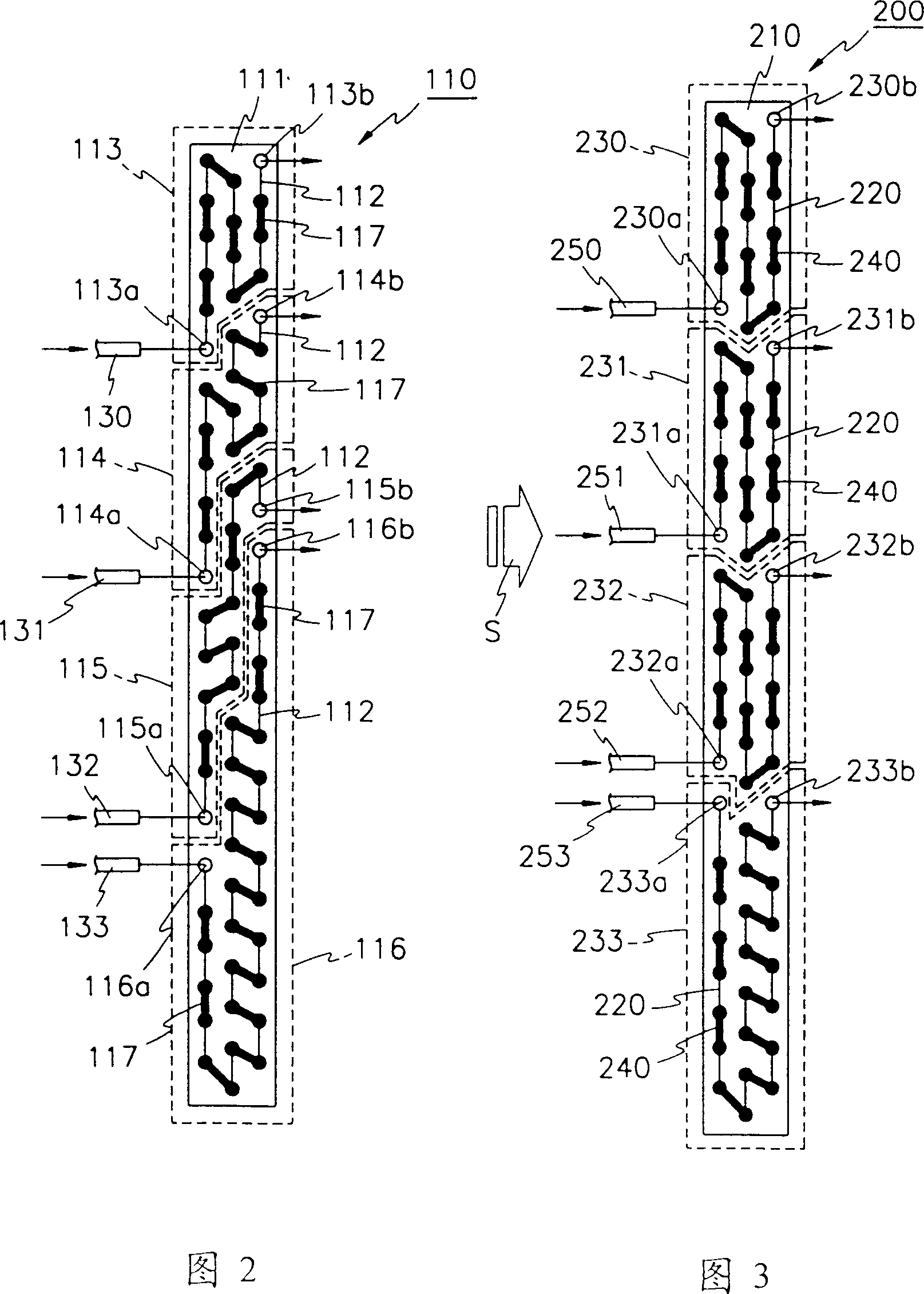
[0017] As shown in FIG. 3, an air conditioner heat exchanger 200 includes: a plurality of flat blades 210 arranged in parallel at a predetermined interval; and a plurality of heat transfer tubes 220 vertically inserted in the plurality of flat blades 210; and first to second Four coolant passage groups 230, 231, 232, and 233 respectively divide a plurality of coolant pipes 220 into two sides (upper and lower sides), each side has a plurality of return hoses 240, and these hoses and their The respective coolant inlet and outlet components are connected.

[0018] Also, the first to fourth coolant passage groups 230, 231, 232, and 233 include respective coolant passage inlet ...


PUM


Abstract

A heat exchanger for an air conditioner is equiped with a first, a second, a third, and a fourth refrigeration stages, each fitted with mutually independent inlets and outlets for the refrigeration stage. A first, a second, a third, and a fourth capillary tubes are provided at the inlets of the refrigeration stages. Accordingly, the heat exchanger being fitted with the four capillary tubes of different lengths ensures that the quantity of refrigerant and air passing through the four refrigeration stages are strictly and mutually suitable and appropriate for the refrigeration stages, maximising by this method the efficiency of the heat exchanger, and it is convenient for return to the tubes to assemble.

Description

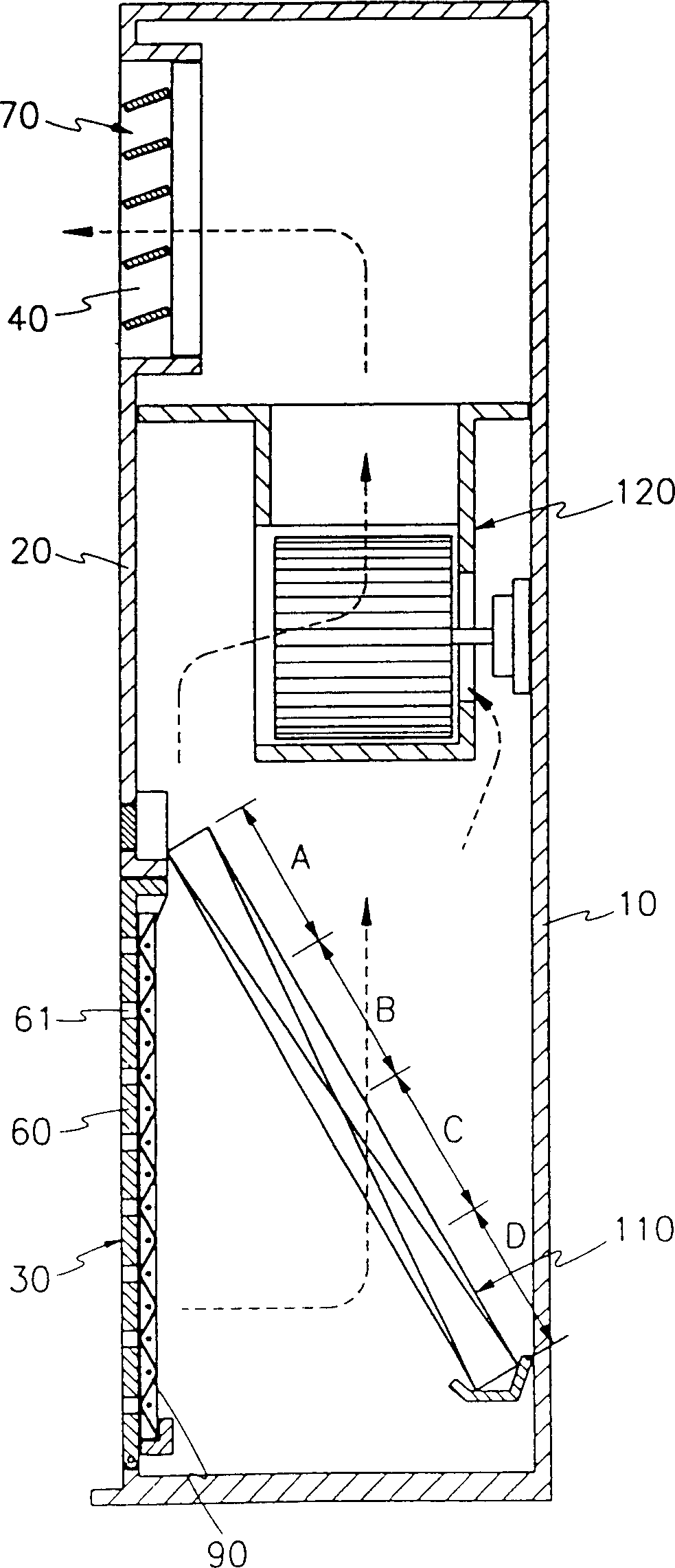
technical field [0001] The present invention relates to an air conditioner heat exchanger, and more particularly, to an air conditioner heat exchanger in which coolant passages of the heat exchanger (for example, an evaporator) are arranged so that each heat exchanger is placed at even intervals, Its multiple capillaries vary in length depending on the air flow. Background technique [0002] An indoor unit of air conditioning, such as figure 1 As shown, it includes: a front panel 20 fixed at the front of a main body 10 for forming the appearance of an air conditioner; a suction port 30 formed at the lower part of the front panel 20 for sucking air into an indoor unit; and a discharge outlet 40 formed on the upper portion of the front panel 20 . [0003] The suction inlet grid body 60 is provided with a plurality of penetration holes 61 to protect the suction inlet 30 and to connect the suction inlet 30 with the air passage, and an air flow control...

Claims


Application Information

Patent Timeline
Patent Type & Authority Patents(China)
IPC IPC(8): F24F1/00F24F13/30F25B39/00F28D1/00F28D1/047F28D11/00F28F9/00
CPCF28D1/0477F28D2021/0071F28F13/06F24F1/0067
Inventor 全济训
Owner SAMSUNG ELECTRONICS CO LTD
Learn More