A radial high frequency vibration type cavitation microplastic forming device

A high-frequency vibration and micro-plastic technology, applied in the direction of feeding device, positioning device, storage device, etc., can solve the problems of low cavitation jet intensity, immature forming technology and forming theory, and inability to meet high forming precision requirements. , to achieve the effects of improving fatigue strength and service life, improving processing and forming efficiency, and reducing energy consumption

Active Publication Date: 2020-06-26
JIANGSU UNIV
View PDF6 Cites 0 Cited by
  • Summary
  • Abstract
  • Description
  • Claims
  • Application Information

AI Technical Summary

Problems solved by technology

However, in the current situation, there are many deficiencies in the traditional mechanical micro-shock technology and laser shock forming technology.
[0004] At present, the cavitation micro-forming technology is relatively novel and environmentally friendly, and has good development prospects, but the forming technology and forming theory are not yet mature, and the processing effect needs to be improved compared with other processing methods. The methods of forming effect include laser cavitation, ultrasonic cavitation, etc., but these methods generally can only induce single bubble collapse, and the cavitation jet intensity is low, which cannot meet the high forming accuracy requirements

Method used

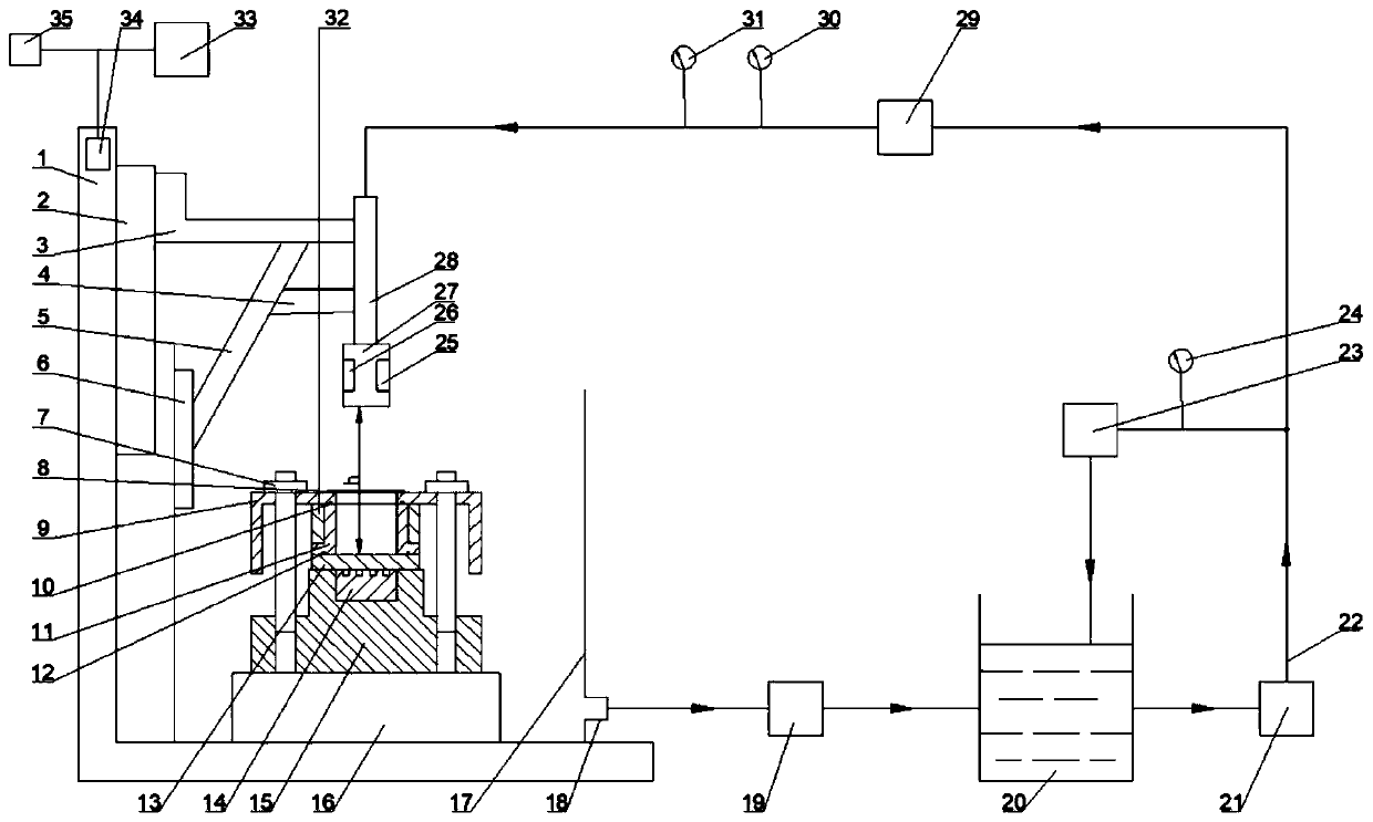
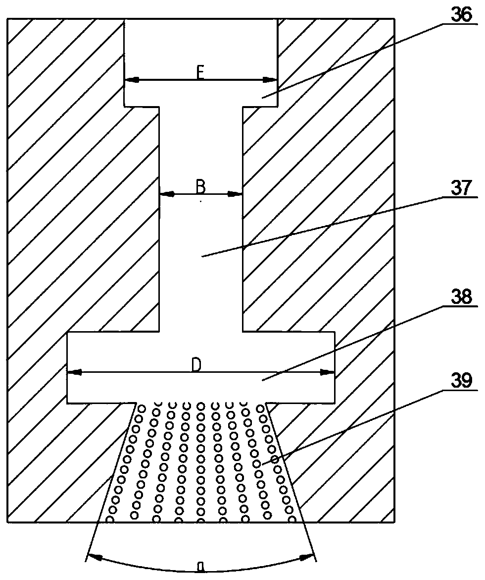
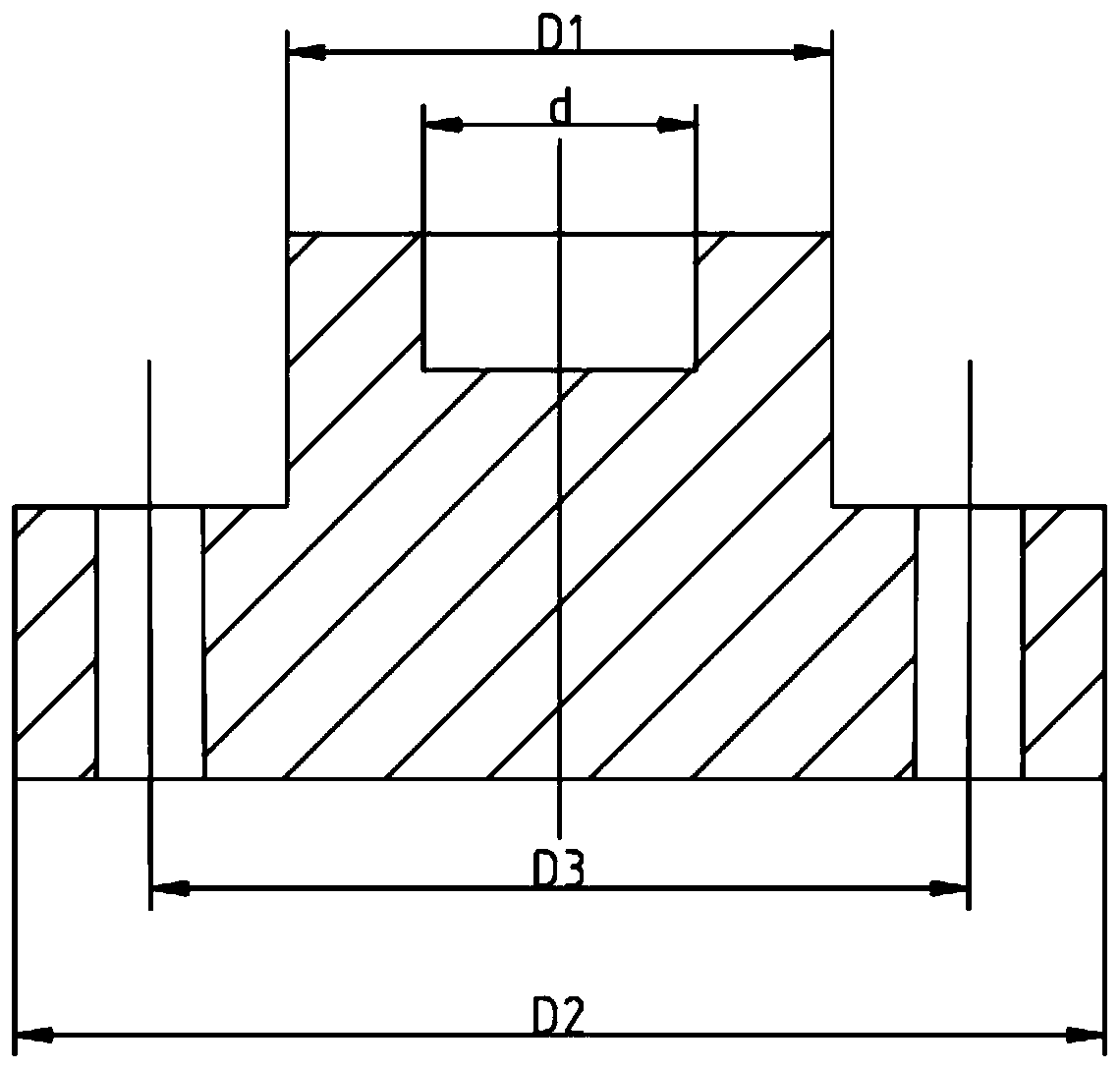

Image

  • A radial high frequency vibration type cavitation microplastic forming device
  • A radial high frequency vibration type cavitation microplastic forming device
  • A radial high frequency vibration type cavitation microplastic forming device

Examples


Embodiment Construction

[0047] Embodiments of the present invention are described in detail below, examples of which are shown in the drawings, wherein the same or similar reference numerals designate the same or similar elements or elements having the same or similar functions throughout. The embodiments described below by referring to the figures are exemplary and are intended to explain the present invention and should not be construed as limiting the present invention.

[0048] In describing the present invention, it is to be understood that the terms "central", "longitudinal", "transverse", "length", "width", "thickness", "upper", "lower", "axial", The orientation or positional relationship indicated by "radial", "vertical", "horizontal", "inner", "outer", etc. is based on the orientation or positional relationship shown in the drawings, and is only for the convenience of describing the present invention and simplifying the description , rather than indicating or implying that the device or elem...


PUM

PropertyMeasurementUnit
elastic modulusaaaaaaaaaa
sizeaaaaaaaaaa

Abstract

The invention provides a radial high-frequency vibration type cavitation micro-plastic forming device. The device comprises a base, a container, a moving mechanism, a clamp mechanism, a jet flow system, a radial high-frequency vibration guide system, a high-frequency signal emitter, a control unit and a computer, wherein the container is positioned on the base; the moving mechanism comprises a horizontal moving workbench and a vertical moving workbench; the clamp mechanism is arranged on the horizontal moving workbench; the jet flow system is used for generating air bubbles and jetting high-pressure jet flow to metal foil to be machined; the radial high-frequency vibration guide system comprises a guide die and a clamping ring, wherein the guide die and the clamping ring are positioned onthe metal foil to be machined, the guide die is made of high-elasticity-modulus rubber, and the clamping ring is positioned on the outer side on the circumferential direction of the guide die; and thecontrol unit is connected with the computer, the moving mechanism, the high-frequency signal emitter and the clamping ring, the control unit is used for controlling the movement of the horizontal moving workbench and the vertical moving workbench and controlling the opening and closing of the clamping ring according to signals of the high-frequency signal emitter. According to the radial high-frequency vibration type cavitation micro-plastic forming device, the induction of cavitation bubble bursting can be intensified, impact waves can be generated, and the impact strength can be improved.

Description

technical field [0001] The invention relates to the technical field of plastic forming of micron-scale shape structures, in particular to a radial high-frequency vibration type cavitation micro-plastic forming device. Background technique [0002] Microforming is one of the manufacturing methods based on the plastic forming process, which can produce parts with dimensions below the order of millimeters in at least two dimensions. With the miniaturization of equipment, the development of micro-electro-mechanical system structural components and precision machining, the demand for short, thin, light, small and other micro-shaped parts continues to increase. However, the difficulty of micro-forming processing is also gradually increasing. On the one hand, it comes from the continuous enhancement of the strength and performance of the processed workpiece, on the other hand, it comes from the continuous refinement and complexity of the structural design of micro-devices. The mic...

Claims


Application Information

Patent Timeline
Patent Type & Authority Patents(China)
IPC IPC(8): B21D26/10B21D43/00B21D33/00
CPCB21D26/10B21D33/00B21D43/003
Inventor 李昊谦王匀李富柱许桢英詹姆斯·夸西·奎西李瑞涛刘宏范海洋于超黄欢於伟杰陈颖亮朱漪云
Owner JIANGSU UNIV
Why Eureka
Try Eureka