
Part transfer device for mechanical manufacturing and production

A technology of mechanical manufacturing and transfer devices, which is applied in the direction of manufacturing tools and workbenches, can solve the problems of inability to transfer for all-round inspection, troublesome inspection of plate parts, unfavorable inspection by inspectors, etc., to reduce the chance of falling off the transfer table Possibility, saving physical strength and time, the effect of reasonable structural design

Pending Publication Date: 2019-09-13
南京宏匡硅材料有限公司
View PDF0 Cites 0 Cited by
  • Summary
  • Abstract
  • Description
  • Claims
  • Application Information

AI Technical Summary

Problems solved by technology

[0003] At present, in the production process of machinery manufacturing, when the quality inspection of some plate parts with a certain weight is carried out on the workbench, because the position of the workbench is relatively fixed, it is troublesome for the inspector to inspect the plate parts and cannot Transshipment conducts all-round inspection, which makes the inspection quality low, time-consuming and laborious, and is not conducive to inspector inspection. Therefore, we propose a parts transfer device for mechanical manufacturing production

Method used


Image

  • Part transfer device for mechanical manufacturing and production
  • Part transfer device for mechanical manufacturing and production
  • Part transfer device for mechanical manufacturing and production

Examples


Embodiment Construction

[0021] The following will clearly and completely describe the technical solutions in the embodiments of the present invention with reference to the accompanying drawings in the embodiments of the present invention. Obviously, the described embodiments are only some, not all, embodiments of the present invention. Based on the embodiments of the present invention, all other embodiments obtained by persons of ordinary skill in the art without creative efforts fall within the protection scope of the present invention.

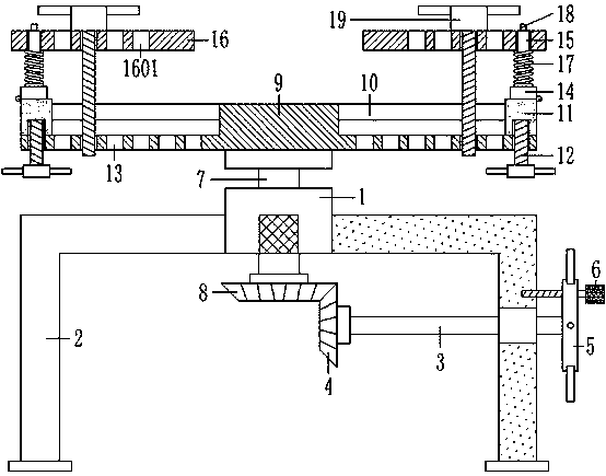
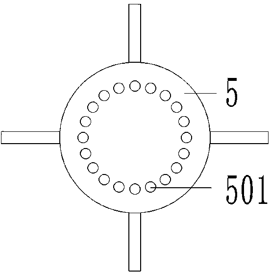
[0022] see Figure 1-3 As shown, a parts transfer device for mechanical manufacturing production, including a bearing seat 1, right-angle support frames 2 are fixedly connected to the front, rear, left, and right side walls of the bearing seat 1, and rubber anti-skid is fixed to the bottom of the four groups of right-angle support frames 2 Pad block, the bottom of the rubber non-slip pad block is provided with anti-slip threads, which increases the friction between...


PUM


Abstract

The invention discloses a part transfer device for mechanical manufacturing and production. The part transfer device comprises a bearing seat. The front side wall, the rear side wall, the left side wall and the right side wall of the bearing seat are fixedly with right-angle supporting frames correspondingly. The left side wall of an inner cavity of the right side right-angle supporting frame is connected with a shaft lever. The left end of the shaft lever is fixedly connected with a main bevel gear. The right end of the shaft lever is fixedly connected with a handle rotary plate. The right side wall of the handle rotary plate is in threaded connection with a limiting bolt pin. The top of the bearing seat is rotationally connected with a support shaft. The bottom of the support shaft is fixedly connected with an auxiliary bevel gear. The auxiliary bevel gear is located under the bearing seat. The top of the support shaft is fixedly connected with a transfer table. The left side wall and the right side wall of the transfer table are symmetrically provided with convex sliding chutes. Convex sliding blocks are slidably connected with inner cavities of the two sets of convex sliding chutes. The left side wall and the right side wall of the bottom of the transfer table are symmetrically connected with handle limiting bolts in a threaded mode. The tops of the two sets of convex sliding blocks are provided with support blocks correspondingly. The part transfer device is reasonable in structure and inspects part transfer, the inspection quality of inspectors is improved, and physical strength and time are saved.

Description

technical field [0001] The invention relates to the technical field of mechanical manufacturing, in particular to a transfer device for parts used in mechanical manufacturing. Background technique [0002] Machinery refers to the general term of machines and mechanisms, and complex machinery is composed of two or more simple machines. Machinery manufacturing refers to various power machinery, lifting and transportation machinery, chemical machinery, textile machinery, machine tools, tools, instruments, etc. The industrial sector that produces instruments, instruments, and other mechanical equipment. The machinery manufacturing industry provides technical equipment for the entire national economy. Parts refer to individual parts that cannot be disassembled in machinery. They are the basic components of machines and the basic components of machinery manufacturing unit. [0003] At present, in the production process of machinery manufacturing, when the quality inspection of so...

Claims


Application Information

Patent Timeline
IPC IPC(8): B25H1/14
CPCB25H1/14
Inventor 李彦李沛霖栗筝李长华马仁宏
Owner 南京宏匡硅材料有限公司
Learn More