
Optical logic "NOT" gate computing system based on time lens imaging

A time lens and computing system technology, applied in the field of optical logic "NO" gate computing system, can solve the problems of low speed of optical logic gate, complex process, complex and cumbersome system, etc.

Active Publication Date: 2019-09-13
ZHEJIANG UNIV OF TECH
View PDF7 Cites 2 Cited by
  • Summary
  • Abstract
  • Description
  • Claims
  • Application Information

AI Technical Summary

Problems solved by technology

[0005] In order to overcome the disadvantages in the prior art of realizing the optical logic operation function through the gain saturation characteristic of semiconductor materials, the technology is complex, the speed of the optical logic gate is not high, and the whole system is complex and cumbersome, the present invention provides a new optical logic based on time lens imaging The "NO" gate operation system not only greatly simplifies the whole system, but also greatly improves the operation rate

Method used


Image

  • Optical logic "NOT" gate computing system based on time lens imaging
  • Optical logic "NOT" gate computing system based on time lens imaging
  • Optical logic "NOT" gate computing system based on time lens imaging

Examples


Embodiment Construction

[0017] The present invention will be further described below through specific embodiments in conjunction with the accompanying drawings, but the protection scope of the present invention is not limited thereto.

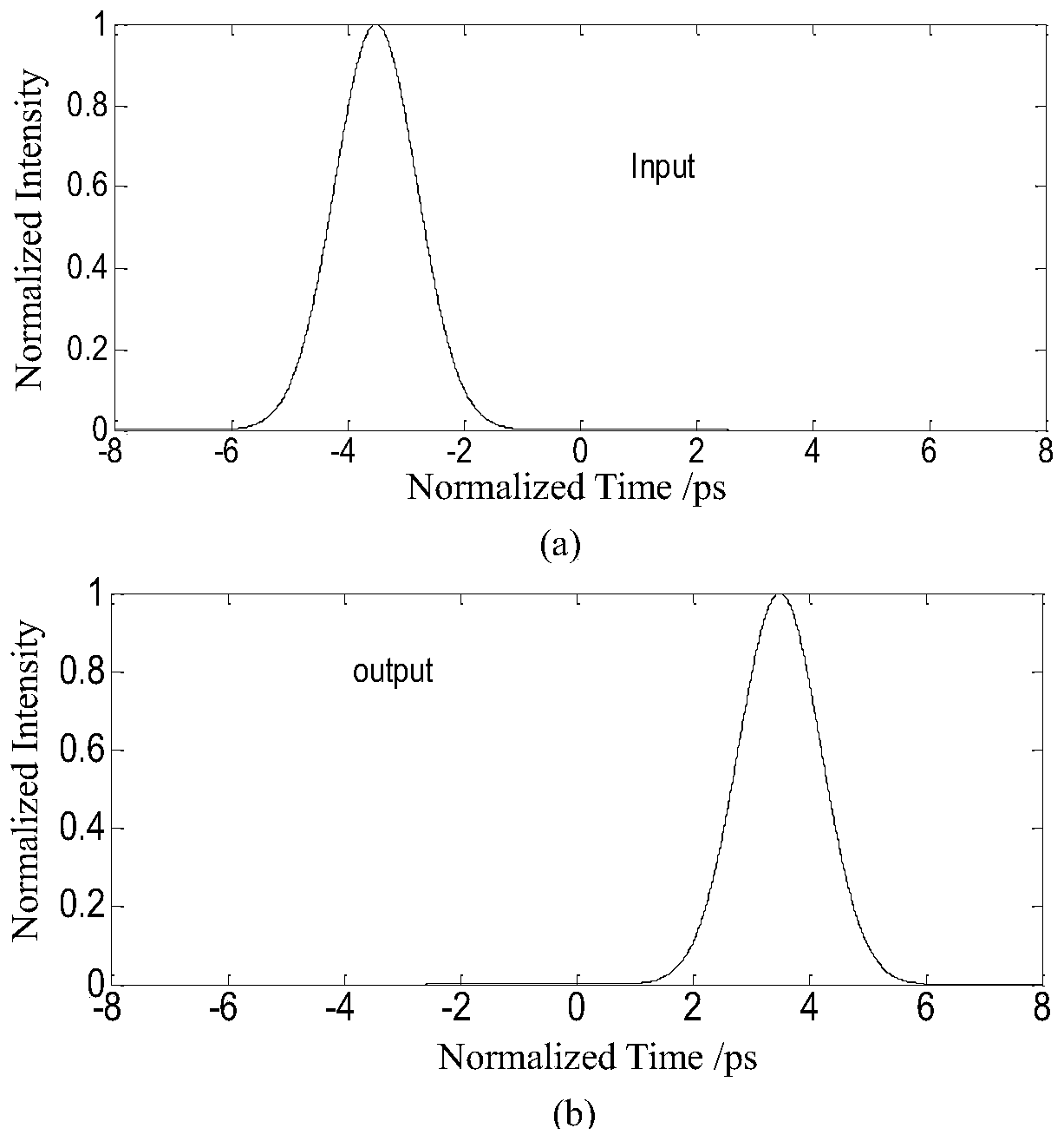
[0018] refer to Figure 1 ~ Figure 3 , an optical logic "NO" gate operation system based on time lens imaging, including a code spreading subsystem, a time lens imaging inversion subsystem and a code reduction subsystem; the code spreading subsystem transforms 1 into 10 and 0 into 01 , this method is very common in the current signal processing and communication fields, so its implementation process will not be repeated here; the time lens imaging inversion subsystem is composed of an input segment optical fiber, a time lens and an output segment optical fiber, and the output The second-order dispersion φ of the segment fiber 2 ″ and the second-order dispersion φ of the input fiber 1 "On the contrary, that is, φ 2 ″=-φ 1 "; The magnification M=φ of the time lens i...


PUM


Abstract

The invention discloses an optical logic "NOT" gate operation system based on time lens imaging. The system comprises an extended code subsystem, a time lens imaging inversion subsystem and a shrink code subsystem. The extended code subsystem enables conversion from "1" to "10" and from "0" to "01". The time lens imaging inversion subsystem realizes inversion of a pulse pair, that is, "10" is inverted to "01", and "01" is inverted to "10". The shrink code subsystem realizes that "01" is restored to "0" and "10" is restored to "1." After the combined effects of the three parts in the system provided by the invention, the logic "NOT" gate calculation is achieved, that is "1" is converted to "0" and "0" is converted to "1". The logic "NOT" calculation system is greatly simplified, and the operation rate is greatly increased.

Description

technical field [0001] The invention relates to an optical logic "NO" gate operation system based on time lens imaging. Background technique [0002] At present, the transmission rate in the optical communication network has reached the Tbit / s level, but the signal processing and switching at the node is limited by the optical switching device, which delays the entire optical network to a certain extent. Optical logic "NOT" gate is one of the basic components of optical logic devices. It can be combined with logical "AND" and logical "OR" to form a variety of complex optical logic operation functions. It is an important device for realizing high-speed all-optical networks. [0003] Time lens refers to an optical device that can generate a second time phase shift for optical signals. For signal processing in the field of optical communication, the first choice is to use four-wave mixing (FWM) to achieve the time lens effect. The magnitude of the electric field is E s (t) an...

Claims


Application Information

Patent Timeline
Patent Type & Authority Applications(China)
IPC IPC(8): G02F3/00H03K19/20
CPCG02F3/00H03K19/20
Inventor 郭淑琴田寒波任宏亮李胜
Owner ZHEJIANG UNIV OF TECH
Learn More