
Sensor module and mobile cleaning robot

A sensor module, camera technology, applied in cleaning machinery, cleaning equipment, machine parts, etc., can solve the problems of small optical range sensor space, easy to change LED, affecting product productivity, etc.

Active Publication Date: 2019-09-13
SHARKNINJA CHINA TECH CO LTD
View PDF10 Cites 1 Cited by
  • Summary
  • Abstract
  • Description
  • Claims
  • Application Information

AI Technical Summary

Problems solved by technology

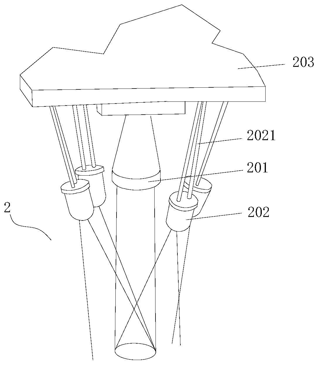
[0006] During the assembly process, due to the interference of other surrounding components, the soldered LEDs are easy to change the angle of each LED, making it deviate from the original set angle, and cannot provide the expected illumination for the telecentric lens, resulting in the telecentric lens Inability to clearly capture images of tracking surfaces;
[0007] The telecentric lens and each of the LEDs are respectively mounted on different mounting structures, and different mounting structures have different processing errors in the process of processing, and the telecentric lens and each of the LEDs are respectively assembled to the There will be different assembly errors in the corresponding installation structure, and the accumulation of errors will cause the angle between each LED and the telecentric lens to change, resulting in possible visible shadows in the captured image;
[0008] The space inside the mobile cleaning robot for installing the optical range sensor is narrow, and the parts used to form the optical range sensor are installed step by step on the robot body of the mobile cleaning robot, which reduces the overall assembly efficiency and affects product productivity

Method used


Image

  • Sensor module and mobile cleaning robot
  • Sensor module and mobile cleaning robot
  • Sensor module and mobile cleaning robot

Examples


Embodiment Construction

[0043] In order to explain the overall concept of the present application more clearly, the following detailed description will be given by way of examples in combination with the accompanying drawings.

[0044] In the following description, many specific details are set forth in order to fully understand the application, but the application can also be implemented in other ways different from those described here, therefore, the protection scope of the application is not limited by the specific details disclosed below. EXAMPLE LIMITATIONS.

[0045] In addition, in the description of the present application, it should be understood that the terms "top", "bottom", "inner", "outer", "axial", "radial", "circumferential" and the like indicate directions or The positional relationship is based on the orientation or positional relationship shown in the drawings, which is only for the convenience of describing the application and simplifying the description, and does not indicate or ...


PUM


Abstract

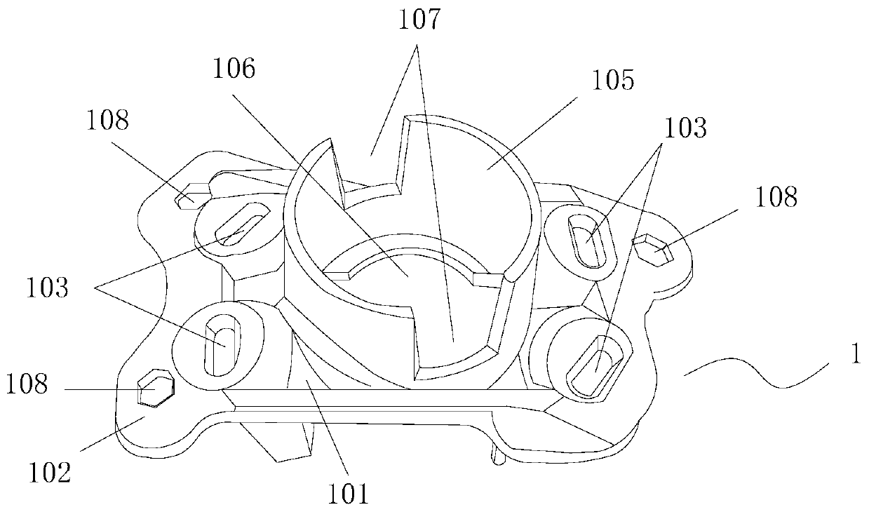
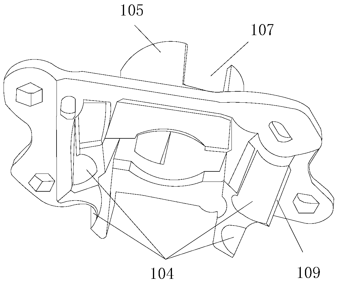
The invention discloses a sensor module, and the module comprises a camera module which comprises an optical range camera, a plurality of illumination elements disposed around the optical range camera, and a circuit board which is electrically connected with the optical range camera and the illumination elements; a first mounting seat, provided with a limiting hole used for limiting the position of the optical range camera and a first limiting part arranged on the periphery of the limiting hole and used for limiting the position of the illumination element. The illumination element is limitedby the first limiting part to enable the included angle between the optical axis of each illumination element and the optical axis of the optical range camera to be an acute angle. The invention further discloses a mobile cleaning robot. The mobile cleaning robot comprises a robot body and the sensor module. The relative fixation of the optical range camera and each illumination element is realized, the change of the relative position between the camera and the illumination element in the assembly process is avoided, and the optical range camera can clearly and accurately capture the image ofthe to-be-tracked surface.

Description

technical field [0001] The application belongs to the technical field of cleaning appliances, and in particular relates to a sensor module and a mobile cleaning robot. Background technique [0002] A mobile robot is a machine device that performs work automatically. It can accept human commands, run pre-programmed programs, and act according to instructions formulated with artificial intelligence technology. Therefore, it has strong self-organization, autonomous operation, and autonomous planning. ability. Mobile robots can be used indoors or outdoors, in industry or at home, can be used to replace security patrols, replace people to clean the ground, and can also be used for family companionship, office assistance, etc., such as medical robots, military robots, disabled robots, patrol robots, cleaning More and more robots are appearing in the public's field of vision. [0003] With the update and iteration of mobile robot mobile technology, VSLAM (Visual Simultaneous Loca...

Claims


Application Information

Patent Timeline
IPC IPC(8): H04N5/225A47L11/24A47L11/40
CPCA47L11/24A47L11/40A47L11/4002A47L11/4011A47L2201/04H04N23/50H04N23/57H04N23/56
Inventor 王旭宁
Owner SHARKNINJA CHINA TECH CO LTD
Learn More