
Hydraulic mixing agitator

An agitator and hydraulic technology, which is used in mixer accessories, mixers with rotating mixing devices, mixers, etc., can solve problems such as deformation of floating disks, easy generation of static electricity, floating disk chucking and sinking disk phenomena.

Inactive Publication Date: 2019-09-17
SINOPEC GUANGZHOU ENG +1
View PDF8 Cites 2 Cited by
  • Summary
  • Abstract
  • Description
  • Claims
  • Application Information

AI Technical Summary

Problems solved by technology

[0005] 1) When the vertical nozzle is blended, when the liquid level is used at a low level, the liquid column will shoot out of the liquid surface, forming "flooding", and the friction between the liquid column and the gas phase in the tank will easily generate static electricity;
[0006] 2) When the vertical nozzle is blended, the liquid column impacts the floating plate, which will cause the deformation of the floating plate, and even cause the chucking and sinking of the floating plate
[0007] 3) After the oil in the oil outlet pipe enters the inner cavity of the tank from the small flow channel area of ​​the oil outlet pipe mouth, the flow channel area is relatively large and open, the flow rate of the liquid at the oil outlet pipe mouth will decrease rapidly, and the oil product will spread in all directions , the energy of a small amount of oil acting on the power blades is negligible, and it is difficult to drive the power blades through the support shaft to achieve the effect of stirring the oil

Method used


Image

  • Hydraulic mixing agitator
  • Hydraulic mixing agitator
  • Hydraulic mixing agitator

Examples


Embodiment Construction

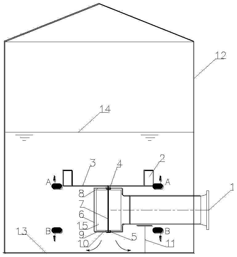
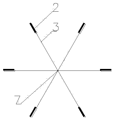
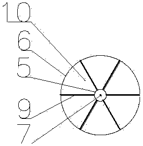
[0026] Such as Figure 1-Figure 4 As shown, a hydraulic blending agitator for a vertical oil storage tank 12 of the present invention includes an oil storage tank 12 and a hydraulic blending agitator, and the hydraulic blending agitator is fixed on the oil storage tank through a pipe bracket 11 In the tank 12, the hydraulic blending agitator includes an equal-diameter tee pipe 6, a rotating shaft 7, an upper bearing 4, a lower bearing 5, a paddle 15 and a stirring blade 2, and the main pipe of the equal-diameter tee pipe 6 is vertical Placement, the upper end is a sealing cover 8, the lower end is an oil outlet 10, a rotating shaft 7 is set at the center line position, the branch pipe of the equal diameter tee pipe 6 is connected to the feed pipe of the oil storage tank 12, and the inlet of the feed pipe is provided with an oil inlet 1. The rotating shaft 7 is placed vertically, and 3 to 5 paddles 15 are evenly distributed along the circumference of the rotating shaft 7. The h...


PUM


Abstract

The invention discloses a hydraulic mixing agitator. The hydraulic mixing agitator comprises an equal-diameter T-pipe, a rotating shaft, an upper bearing, a lower bearing, blades and a stirring blade, wherein a main pipe of the equal-diameter T-pipe is vertically placed, the upper end of the main pipe is provided with a sealing cover, a rotating shaft is vertically arranged at the center line position of the main pipe, the rotating shaft is provided with 3-5 blades, the height of the blades is smaller than the length of the main pipe of the equal-diameter T-pipe, the diameter of an envelope line of each blade is smaller than the diameter of the main pipe of the equal-diameter T-pipe, the upper end of the rotating shaft passes through the upper bearing and then is fixedly connected with the stirring blade through 4-8 rotating arms, the lower end of the rotating shaft is placed in the lower bearing, and the lower bearing is fixed at the center of an outlet outlet of the equal-diameter T-pipe through 4-8 bearing fixing brackets. By using the hydraulic mixing agitator, the blending of oil in a tank during normal production can be realized, leakage is avoided, furthermore 'flooding' does not occur, a floating tray cannot be impacted, and the floating disc is prevented from getting stuck and sinking.

Description

technical field [0001] The invention belongs to the field of oil product storage and transportation systems for petrochemical enterprises, and relates to a hydraulic blending agitator. Background technique [0002] Oil blending in tanks is an important process in the production operation of oil storage and transportation systems in petrochemical enterprises. The existing blending methods mainly include: side agitator blending and nozzle blending. [0003] The Chinese patent No. 201120214409.5 discloses a side agitator, which includes a bracket, a motor, a flange, an impeller, a main shaft and a reduction box. The bracket includes a vertical plate and a horizontal plate, and the motor is fixedly arranged on the horizontal plate. The outer side of the vertical plate is fixed with a fixed seat, the reduction box is fixedly set on the fixed seat, the output end of the motor is connected with the input end of the reduction box, the output end of the reduction box is connected wi...

Claims


Application Information

Patent Timeline
Patent Type & Authority Applications(China)
IPC IPC(8): B01F15/00B01F7/04
CPCB01F27/70B01F2035/351B01F35/32015B01F35/45
Inventor 程继元郭维军何龙辉李战杰李津何钦全
Owner SINOPEC GUANGZHOU ENG
Learn More