

Automatic assembling system for cable tray
An automatic assembly and cable reel technology, applied in the direction of assembly machines, manufacturing tools, metal processing, etc., can solve the problems of low efficiency, time-consuming and laborious, etc., and achieve the effect of labor saving, high efficiency and fast assembly speed
- Summary
- Abstract
- Description
- Claims
- Application Information
AI Technical Summary
Problems solved by technology
Method used
Image

Examples
Embodiment Construction
[0019] The present invention will be further described below in conjunction with the accompanying drawings, but the protection scope of the present invention is not limited to the following description.
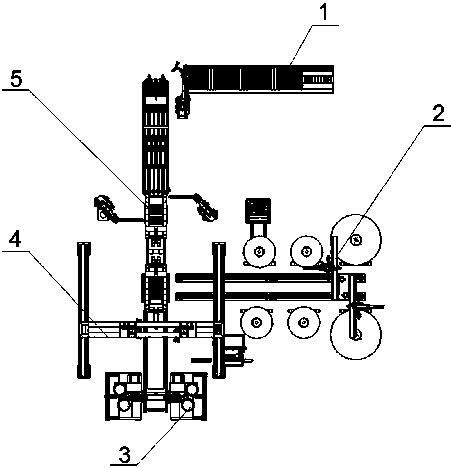
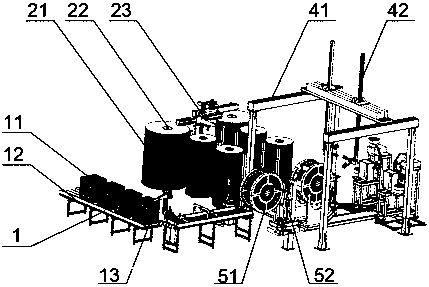
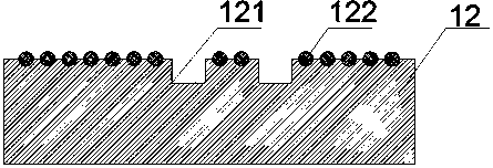
[0020] Such as Figure 1-4 As shown in the figure, an automatic cable tray assembly system includes a frame and a control system. The frame is equipped with a core board feeding station (1), a disk feeding station (2) and a core board forming Work station (5), the core board feeding station (1) includes a core board conveyor belt (12) and a core board extraction robot (13) arranged on one side of the core board conveyor belt (12); The station (2) includes the disk moving device, the disk loading rack (22) and the disk turning and positioning gripper (23) arranged on the disk moving device; the two sides of the core board forming station (5) are respectively connected to The core plate conveyor belt (12) and the disk moving device; the lower end of the core plate forming stat...
PUM
 Abstract
Description
Claims
Application Information