Repair tools after pothole detection

A post-detection technology for potholes, which is applied in road repair, roads, construction, etc., can solve the problems of edge effects of filling effects and construction efficiency, and achieve the effects of easy filling, high construction efficiency, and good cutting effect

Active Publication Date: 2020-12-04
内蒙古路桥工程技术检测有限责任公司
View PDF1 Cites 0 Cited by
  • Summary
  • Abstract
  • Description
  • Claims
  • Application Information

AI Technical Summary

Problems solved by technology

The above-mentioned pothole repair vehicle does not have a cutting function, so relevant personnel are required to cut the edge of the pit in advance, which affects the overall construction efficiency. At the same time, the later filling effect is also easily affected by the effect of manually cutting the edge of the pit.

Method used


Image

  • Repair tools after pothole detection
  • Repair tools after pothole detection
  • Repair tools after pothole detection

Examples


Embodiment 1

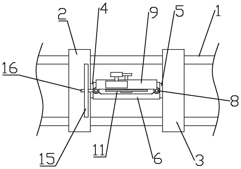
[0030] Such as figure 1 As shown, this embodiment discloses a repairing tool after pothole detection, a repairing tool after pothole detection, including a main vehicle body capable of locking the position, and a machine vision component for measuring the edge of the pothole is provided on the main vehicle body , a material storage assembly for placing fillers, a filling assembly for conveying fillers in the pit, and a leveling assembly (not shown in the accompanying drawings) for leveling and repairing the surface of the pit, the bottom of the main body is set There is a cutting assembly for cutting the edge of the pit groove, and the position of the main vehicle body corresponding to the cutting assembly is opened to facilitate the operation of the operator.

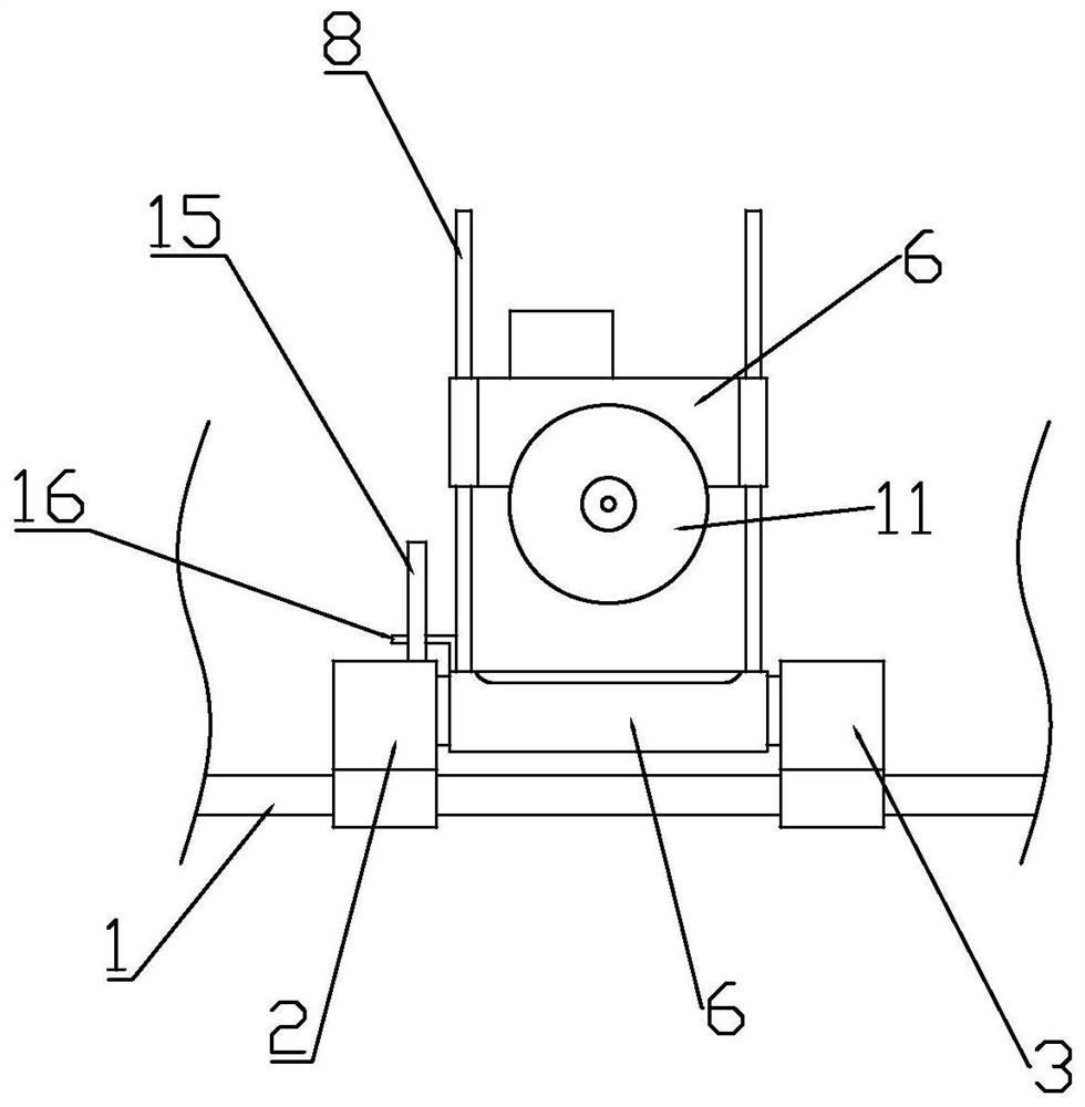
[0031] The cutting assembly includes two first optical axes 1 horizontally arranged on the bottom surface of the main vehicle body. The first optical axis 1 is pierced with a first base 2 and a second base 3 through a ...

Embodiment 2

[0046] refer to Figure 7 , the difference between this embodiment and embodiment 1 is:

[0047] The opposite sides of the first base 2 and the second base 3 are provided with several horizontal buffer springs 20, the horizontal buffer springs 20 are in the same direction as the first optical axis 1; the saw blade frame 9 is located outside the range of the first passing groove 7 Several vertical buffer springs 21 are provided, and the vertical buffer springs 21 are in the same direction as the second optical axis 8 .

[0048] Compared with Embodiment 1, this embodiment is equipped with buffer springs on the first optical axis and the second optical axis, so that both the edge of the cutting track and the depth of cutting are more controllable during cutting, and in the non-working state , the cutting assembly is located relatively in the middle of the entire assembly to protect the cutting saw blade and prolong its service life.

Embodiment 3

[0050] refer to Figure 8 with Figure 9 , the difference between this embodiment and embodiment 1 is:

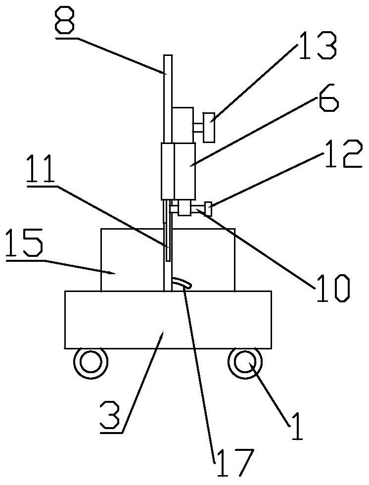
[0051] The first base 2 and the second base 3 are also provided with a horizontal lead screw 22 parallel to the first optical axis 1 through the lead screw nut. The vertical leading screw 23, the end of horizontal leading screw 22 and vertical leading screw 23 are respectively connected with the stepper motor 24 that is fixed on the main vehicle body and on the hollow shaft 6.

[0052] Compared with Embodiment 1, this embodiment adds a horizontal lead screw for driving the cutting assembly to move in the x-axis direction in the first base and the second base, and adds a horizontal lead screw for driving the cutting assembly to move in the x-axis direction on the saw blade frame. The vertical lead screw moving in the z-axis direction is controlled by a stepping motor, so that it can be intelligently controlled by a single-chip microcomputer, without manual cutting, which i...


PUM


Abstract

The invention discloses a repair tool after pit slot detection. The repair tool comprises a vehicle body capable of locking a position. The vehicle body is provided with a machine vision assembly for measuring the edge of a pit slot, a storage assembly for placing a filler, a filling assembly for conveying the filler in the pit slot and a leveling assembly for leveling the surface of the repaired pit slot, and a cutting assembly for cutting the edge of the pit slot is arranged at the bottom of the vehicle body. According to the repair tool after pit slot detection, cutting of road surface around the pit slot can be completed, the cutting effect is good, the later filling work is convenient, and the overall construction efficiency is high.

Description

technical field [0001] The invention belongs to the technical field of road surface maintenance, and further relates to a road surface maintenance equipment, in particular to a repair tool after pit detection. Background technique [0002] Pot holes on the pavement refer to the potholes caused by partial shedding of pavement aggregates under the action of driving. If maintenance and repairs are not timely, it will pose a great threat to driving safety, and at the same time, it will aggravate the increase in maintenance costs. The existing pothole repair generally follows the principle of square repair for round holes and positive repair for inclined holes, so that the repair surface is rectangular, and the surroundings are parallel or perpendicular to the road markings. The scope can be expanded to the surrounding areas according to the actual scope of surface diseases. [0003] Chinese patent CN105463973A discloses an intelligent pothole repair vehicle, which collects the ...

Claims


Application Information

Patent Timeline
Patent Type & Authority Patents(China)
IPC IPC(8): E01C23/09E01C23/06
CPCE01C23/065E01C23/0966
Inventor 李军闫旭亮李永翔何永李伟于敏彭俊李峰蔺美龙马飞
Owner 内蒙古路桥工程技术检测有限责任公司
Why Eureka
Try Eureka