Cast-in-situ bored pile structure and construction method thereof

A technology of bored cast-in-place piles and cast-in-place holes, which is applied in basic structural engineering, sheet pile walls, buildings, etc., can solve the problems of uneven friction of steel casings, reducing the quality of cast-in-place piles, and poor verticality of steel cages. Achieve the effect of improving stability and final forming quality, improving stable guiding effect, and small axis offset

Inactive Publication Date: 2019-09-17
天津弘野建设集团有限公司
View PDF10 Cites 10 Cited by
  • Summary
  • Abstract
  • Description
  • Claims
  • Application Information

AI Technical Summary

Problems solved by technology

[0004] In the above construction process, the steel casing is directly inserted into the pouring hole. Therefore, during the process of the steel cage below, the friction between the steel cage and the steel casing will drive the steel casing to settle, and the steel casing will be affected. The friction force of the steel casing is not uniform, so the axis of the steel casing and the axis of the pouring hole will deviate, which makes the verticality of the lower part of the steel cage poor, and reduces the forming quality of the cast-in-place pile

Method used


Image

  • Cast-in-situ bored pile structure and construction method thereof
  • Cast-in-situ bored pile structure and construction method thereof
  • Cast-in-situ bored pile structure and construction method thereof

Examples


Embodiment 1

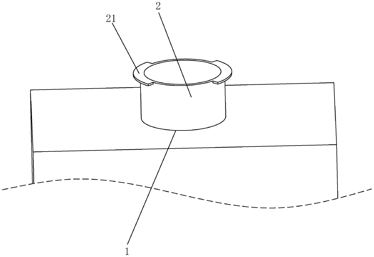
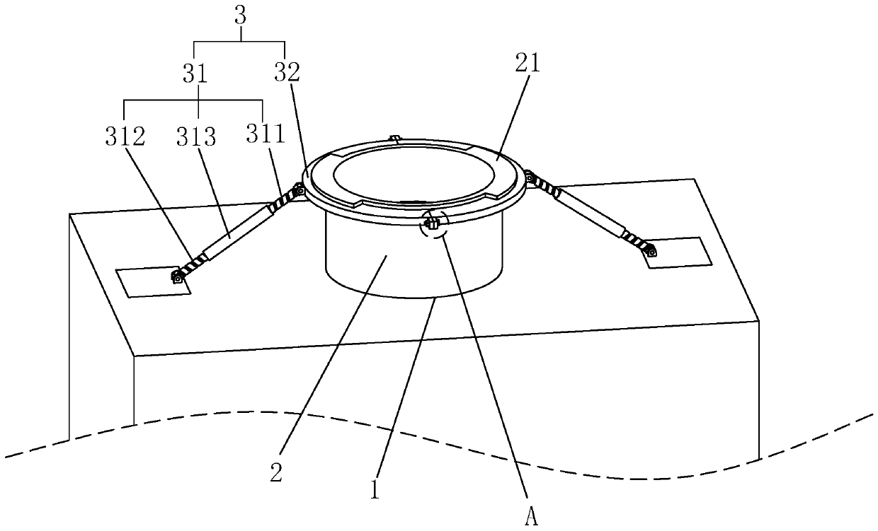
[0044] A bored pile structure, such as Figure 4 As shown, it includes the filling hole 1 opened on the ground. A steel casing 2 is inserted at the top opening of the filling hole 1. The steel casing 2 is attached to the inner wall of the filling hole 1. A reinforcement cage 5 is provided, and the reinforcement cage 5 passes through the steel casing 2 from top to bottom, and the outer surface of the steel casing 2 is clamped with a positioning assembly 3 for preventing the steel casing 2 from settling. During construction, first dig a hole on the ground and bury the steel casing 2, then continue to dig holes along the inside of the steel casing 2, and then put the reinforcement cage 5 into the pouring hole 1 along the steel casing 2 after the hole is dug. In the process of lowering the reinforcement cage 5, the positioning component 3 can fix the steel casing 2, so that the lowering stability of the reinforcement cage 5 is higher, thereby improving the final forming quality of...

Embodiment 2

[0051] A construction method for a bored pile structure, comprising the following construction steps:

[0052] S1. Clean up the ground and tamp the position where the cast-in-situ pile needs to be formed, and prefabricate the reinforcement cage 5 in advance;

[0053] S2. Drill a hole with a depth of 2-4m and bury a steel casing 2. The inner diameter of the steel casing 2 is selected to be 20-40cm larger than the pile diameter;

[0054] S3, two vertical guide columns 4 are set around the drilled holes to ensure that the distances between the two guide columns 4 and the axis of the steel casing 2 are equal;

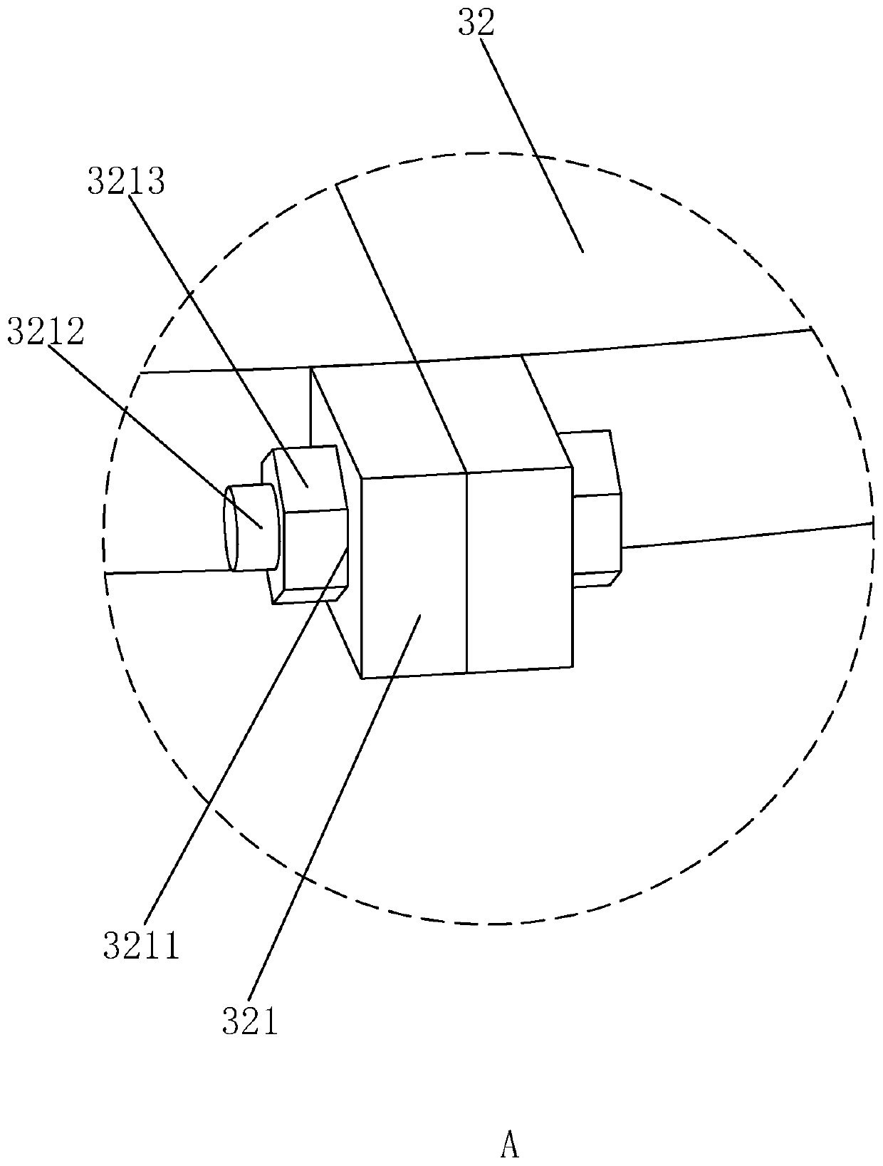
[0055] S4. Install the positioning component 3: connect the second adjusting screw 312 to the ground hinge, then abut the positioning ring 32 on the outer wall of the steel casing 2 and ensure that the top of the positioning ring 32 is in contact with the blocking piece 21, and lock the bolt 3212 After passing through the locking hole 3211, screw on the locking nut 3213; ...


PUM


Abstract

The invention relates to a cast-in-situ bored pile structure and a construction method thereof, and belongs to the technical field of cast-in-situ piles. According to the key points of the technical scheme, the cast-in-situ bored pile structure comprises a pouring hole formed in the ground, a steel casing is arranged on the hole wall, close to the top end, of the pouring hole in an inserted mode, two mutually opposite blocking sheets are fixedly arranged at the edge of the top end of the steel casing, positioning assemblies are arranged on the two opposite sides of the pouring hole in the diameter direction of the pouring hole and comprise positioning rods and positioning rings, each positioning ring is in a semicircular shape attached to the outer wall of the steel casing, one ends of the positioning rods are in hinged connection with the positioning rings, the other ends of the positioning rods are in hinged connection with the ground, when the two positioning rings abut against the outer wall of the steel casing, the top ends of the positioning rings abut against the blocking sheets, the two positioning rings are in a circular ring shape with the outer diameter being equal to the outer diameter of the steel casing, and the two positioning rings are detachably and fixedly connected. The effect of improving the forming quality of the cast-in-situ pile is realized.

Description

technical field [0001] The invention relates to the technical field of cast-in-situ piles, in particular to a bored cast-in-place pile structure and a construction method thereof. Background technique [0002] Cast-in-situ pile refers to the pile hole formed in the foundation soil by means of mechanical drilling, steel pipe extrusion or manual excavation at the project site, and a steel cage is placed in it and concrete is poured into the pile. According to different hole-forming methods, Cast-in-situ piles can be divided into several categories such as immersed pipe piles, bored piles and bored piles. [0003] The existing cast-in-situ pile construction process includes the following steps: first level the site and prepare mud, then dig holes on the ground and bury the steel casing, insert the steel casing, and then use the rotary drilling rig to go down from the steel casing Continue to dig out the pouring hole. After the pouring hole reaches the specified depth, put the ...

Claims


Application Information

Patent Timeline
Patent Type & Authority Applications(China)
IPC IPC(8): E02D5/38E02D15/08
CPCE02D5/38E02D5/385E02D15/08E02D2200/16E02D2200/1614
Inventor 邱中全
Owner 天津弘野建设集团有限公司
Why Eureka
Try Eureka