A thermal power plant emergency protection partition wall

A technology for thermal power plants and emergencies, applied in the direction of walls, building components, fire rescue, etc., can solve the problems of reducing the work efficiency of thermal power plant staff, inconvenience, difficult isolation and protection, etc., to improve the escape success factor and facilitate escape. , the effect of improving convenience

Active Publication Date: 2020-08-18
大唐东营发电有限公司
View PDF6 Cites 0 Cited by
  • Summary
  • Abstract
  • Description
  • Claims
  • Application Information

AI Technical Summary

Problems solved by technology

[0003] The separation wall in the prior art cannot effectively realize flexible adjustment when isolating and protecting the thermal power plant, making it difficult for the thermal power plant to achieve the storage effect while performing isolation and protection in emergencies and emergencies, thus giving the thermal power plant It brings great inconvenience to the staff, greatly reduces the work efficiency of the thermal power plant staff, so it cannot meet the needs of the existing technology

Method used


Image

  • A thermal power plant emergency protection partition wall
  • A thermal power plant emergency protection partition wall
  • A thermal power plant emergency protection partition wall

Examples


Embodiment 1

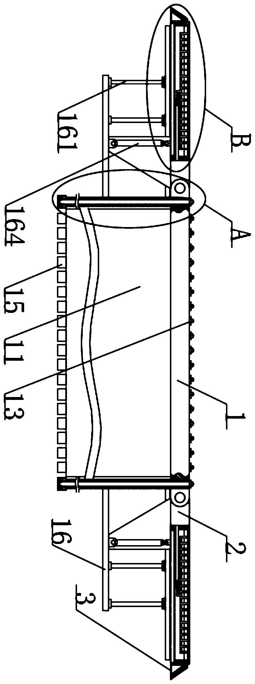
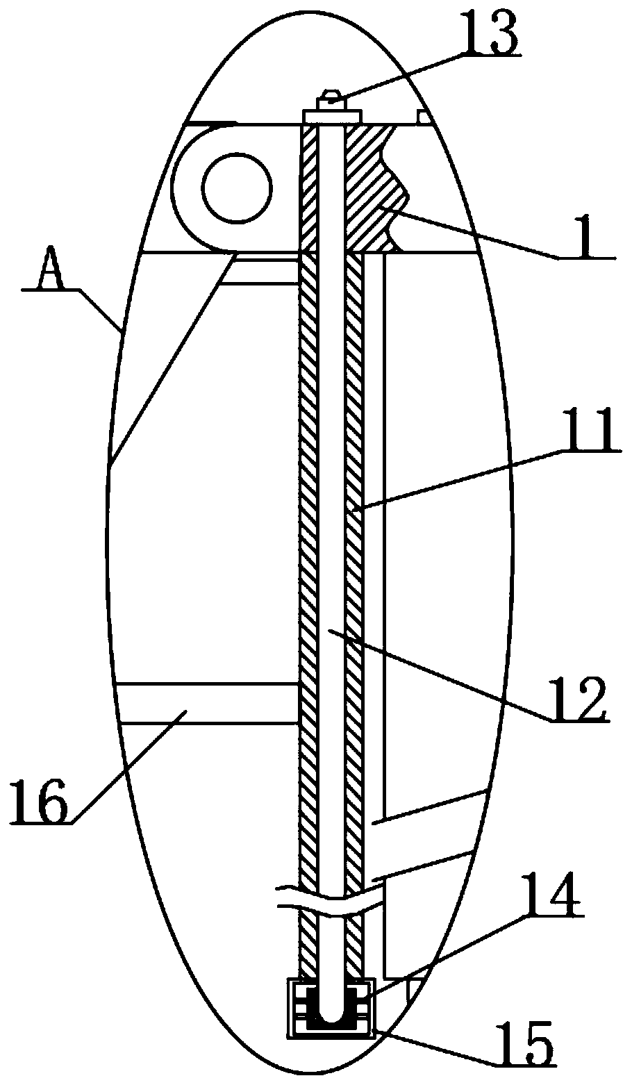
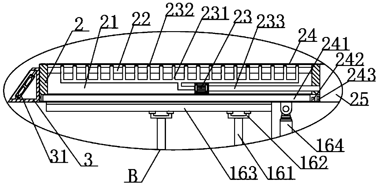
[0026] see Figure 1-6, the present invention provides a technical solution: an emergency protection partition wall of a thermal power plant, including a fixed frame 1 and a partition wall 2, and the partition wall 2 also includes a controller 243. A solar cell panel 24 is fixedly connected by bolts, and the model of the solar cell panel 24 is a solar cell panel of DL-Z500W, and a battery 241 is fixedly connected to the inside of the partition wall 2 near the bottom end by bolts, and the model of the battery 241 is The storage battery of L2-400MF, the inside of the separation wall 2 on the side of the storage battery 241 is respectively fixedly connected with a photovoltaic converter 242 and a controller 243 by bolts, and the model of the controller 243 is a controller of BF-8805A. The photovoltaic converter 242 is a photovoltaic converter whose model is Snaterm-P-1000. When the fixed frame 1 is in a horizontal position, that is, when the electrohydraulic push rod 164 is in a ...

Embodiment 2

[0028] see Figure 1-6 , the present invention provides a technical solution: an emergency protection partition wall of a thermal power plant, including a fixed frame 1 and a partition wall 2, and the partition wall 2 also includes a controller 243. A solar cell panel 24 is fixedly connected by bolts, and the model of the solar cell panel 24 is a solar cell panel of DL-Z500W, and a battery 241 is fixedly connected to the inside of the partition wall 2 near the bottom end by bolts, and the model of the battery 241 is The storage battery of L2-400MF, the inside of the separation wall 2 on the side of the storage battery 241 is respectively fixedly connected with a photovoltaic converter 242 and a controller 243 by bolts, and the model of the controller 243 is a controller of BF-8805A. The photovoltaic converter 242 is a photovoltaic converter whose model is Snaterm-P-1000. When the fixed frame 1 is in a horizontal position, that is, when the electrohydraulic push rod 164 is in a...


PUM


Abstract

The invention discloses a protection isolation wall for emergencies of thermal power plants. The protection isolation wall comprises a fixed frame and isolation wall bodies; the periphery of the lower surface of the fixed frame is fixedly connected with fixing inserting plates through bolts; and the positions, close to the top ends, of the middles of one sides of the fixing inserting plates are fixedly connected with supporting plates through bolts. Through guiding pipes arranged in the fixed frame and the fixing inserting plates, and water pumping pipes and dredge pipes arranged in the isolation wall bodies through water pumps, water suction pumps at the bottom ends of the fixing inserting plates can convey water body resources into the fixed frame and the isolation wall bodies to protect the solation wall bodies, and meanwhile the thermal power plants in the four solation wall bodies or equipment in the thermal power plants can further be subjected to fire extinguishing protection; and meanwhile, workers in the thermal power plants are wet when leaving and escaping through protection plates, thus convenience of the workers during escaping is effectively improved, then the escaping success coefficient is increased, and then the defects in the prior art are effectively made up.

Description

technical field [0001] The invention relates to the technical field of separation walls, in particular to a thermal power plant emergency protection separation wall. Background technique [0002] A thermal power plant, referred to as a thermal power plant, is a factory that uses combustibles as fuel to produce electricity. Its basic production process is to heat water to generate steam when the fuel is burned, and convert the chemical energy of the fuel into heat energy. The steam pressure drives the steam turbine to rotate, and the heat energy is converted. Then the steam turbine drives the generator to rotate, and converts the mechanical energy into electrical energy to generate electricity. The isolation wall is a kind of isolation protection device, which can effectively achieve the effect of isolation protection. The isolation wall can effectively improve the production safety of thermal power plants coefficient, to avoid unnecessary accidents caused by emergencies or e...

Claims


Application Information

Patent Timeline
Patent Type & Authority Patents(China)
IPC IPC(8): E04B2/74E04B2/82A62C31/02
CPCA62C31/02E04B2/7411E04B2/82
Inventor 李玮陈增辉贾长武倪培林赵建宁魏厚玉安娜李政阳
Owner 大唐东营发电有限公司
Why Eureka
Try Eureka