
Active and passive coupling support system for large deformation mining roadway and construction method thereof

A technology of mining roadway and coupling support, which is applied in the direction of supporting the roof beam of the mine roof, mining equipment, earthwork drilling and mining, etc., can solve the problems of support structure failure, roadway roof collapse, collapse, etc., and achieve the purpose of strengthening roadway support, Solve the effect of large deformation and prevent the bottom drum

Inactive Publication Date: 2019-09-17
SHANDONG UNIV OF SCI & TECH
View PDF11 Cites 8 Cited by
  • Summary
  • Abstract
  • Description
  • Claims
  • Application Information

AI Technical Summary

Problems solved by technology

[0003] The purpose of the present invention is to provide a large deformation mining roadway active and passive coupling support system and construction method to overcome the problems of support structure failure, roadway roof fall and collapse caused by the large deformation of the roadway in the above-mentioned prior art

Method used


Image

  • Active and passive coupling support system for large deformation mining roadway and construction method thereof
  • Active and passive coupling support system for large deformation mining roadway and construction method thereof
  • Active and passive coupling support system for large deformation mining roadway and construction method thereof

Examples


Embodiment Construction

[0033] The present invention will be further described below in conjunction with the accompanying drawings and embodiments.

[0034] The structures, proportions, sizes, etc. shown in the drawings attached to this specification are only used to match the content disclosed in the specification for the understanding and reading of those who are familiar with this technology, and are not used to limit the conditions for the implementation of the present invention , so it has no technical substantive meaning, and any modification of structure, change of proportional relationship or adjustment of size shall still fall within the scope of the disclosure of the present invention without affecting the functions and objectives of the present invention. The technical content must be within the scope covered. At the same time, terms such as "upper", "lower", "left", "right", "middle" and "one" quoted in this specification are only for the convenience of description and are not used to lim...


PUM


Abstract

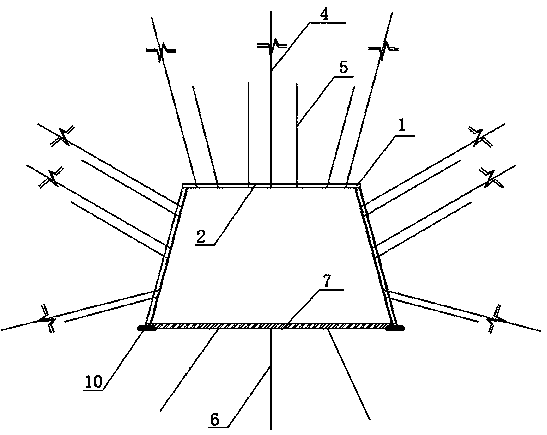
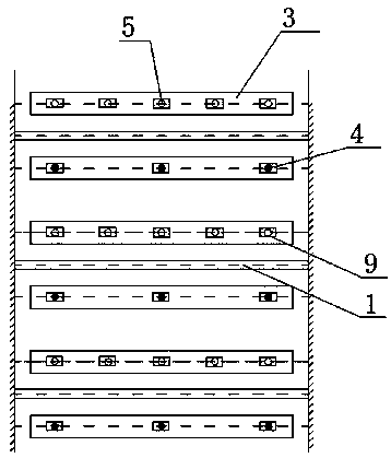
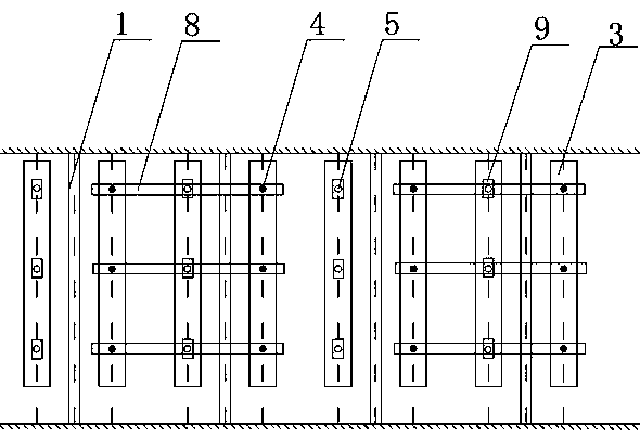
The invention discloses an active and passive coupling support system for a large deformation mining roadway. The active and passive coupling support system comprises mine I-beam brackets for supporting surrounding rock of a roadway along a roof and two sides of the roadway and matched with the inner surface of the surrounding rock of the roadway, a metal mesh is arranged between the surrounding rock of the roadway and a mine I-beam; W steel strips are arranged on the inner surface of the metal mesh in a laying mode, high-strength trays are arranged on the outer surfaces of the W steel strips; anchor rods on the roof and the two sides of the roadway penetrate through the trays, the W steel strips and metal mesh to be driven into the surrounding rock of the roadway from the inner surface of a stopping roadway; the inner surface, extending out of the roadway, of the surrounding rock of the roadway is fixed by the high-strength trays; trimming beams are arranged on the two sides of the roadway, anchor cables on the two sides of the roadway penetrate through the trimming beams, the W steel strips and the metal mesh from the inner surface of the stopping roadway to be driven into the surrounding rock of the roadway, and the inner surfaces, extending out the inner surface of the surrounding rock of the roadway, of the anchor cables are fixed by the trimming beams; the anchor cable at the top of the roadway penetrates through the trays, the W steel strips and the metal mesh from the inner surface of the stopping roadway to be driven into the surrounding rock of the roadway; and the inner surfaces, extending out the surrounding rock of the roadway, of the anchor cables are fixed by the tray. The invention further discloses a construction method of the active and passive coupling support system.

Description

technical field [0001] The invention relates to a mine roadway support technology, in particular to an active and passive coupling support system and a construction method for a large deformation mining roadway. Background technique [0002] The large deformation of the surrounding rock of the mining roadway is one of the important problems that plague the safe and efficient production of coal mines. In production practice, there is no good solution to the characteristics of large deformation, high stress and difficult support of the mining roadway. Chinese patent 201811377228.7 discloses the three-zone collaborative coupling support system and construction method of the broken surrounding rock roadway. However, this technology uses bolts for support. Due to the limitation of the length of the bolt, it will be difficult for the mining roadway with a wide distribution of plastic zones. Difficult to control roadway surrounding rock damage; Chinese patent 2017111392527.2 disclo...

Claims


Application Information

Patent Timeline
Patent Type & Authority Applications(China)
IPC IPC(8): E21D17/01E21D20/02E21D21/00
CPCE21D17/01E21D20/02E21D21/0026
Inventor 郝建边华吴文兵秦哲张晟张广超蒋邦友张禹王腾飞
Owner SHANDONG UNIV OF SCI & TECH
Learn More