[0022] Next, the present invention will be further described in conjunction with the accompanying drawings.
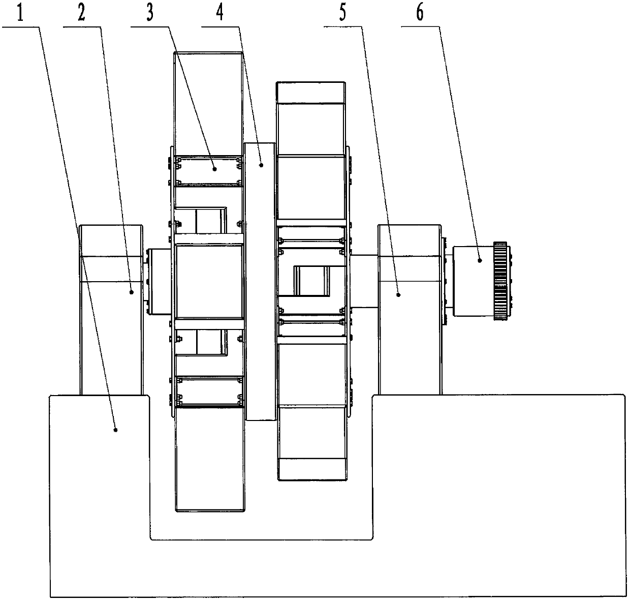
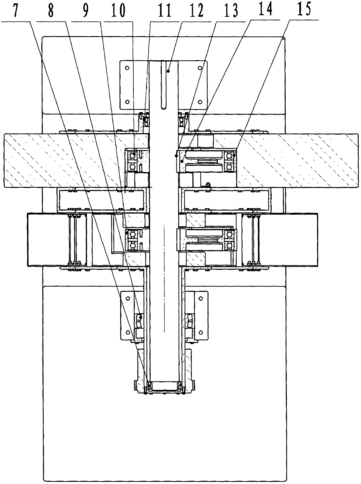
[0023] like Figure 1 to Figure 3 As shown, a center-of-gravity translation engine according to a specific embodiment of the present invention is used to drive the generator to run and generate electricity after being connected with a transmission and a generator. The center-of-gravity translation engine includes: a support device, a spoke (4), a fixed shaft (12) , concave slider (16), eccentric wheel (9) and coupling (6); one end of the spoke (4) is provided with a bearing cup (23), and is set on the fixed shaft (12) through the bearing (11) , the other end of the spoke (4) is provided with a hollow shaft (18), and is sleeved on the fixed shaft (12) through the bearing (7) in the hollow shaft (18), and then passes through the bearing (8) outside the hollow shaft (18) ) is assembled in the bearing seat (5); one end of the fixed shaft (12) is fixed in the positioning seat (2) by a key (17), and the other end passes through the spoke (4) and two eccentric wheels (9) in sequence, and The bearing (7), the hollow shaft (18) and the large bearing (8) are assembled in the bearing seat (5), and the two eccentric wheels (9) are fixed on the fixed shaft (12) through the key (13), and The connecting line between the center lines of 2 eccentric wheels (9) and the center of the eccentric hole is kept horizontal; the middle part of the keyway plate (30) in 8 concave slide blocks (16) is provided with a 12) hole type keyway (28), so that the concave slider (16) assembled in the slider guide frame (3) can pass through the fixed shaft (12) and overlap on the outer circumference of the eccentric wheel (9); Among them, a plurality of concave sliders (16) are restricted by the slider guide frame (3) and the eccentric wheel (9) in the spokes (4), so that the center of gravity produces a horizontal translation, and the concave sliders (16) ) can generate reciprocating motion in the slider guide frame (3), thereby driving the spokes (4) and the hollow shaft (18) to rotate clockwise, thereby enabling the hollow shaft (18) to drive the engine to run and generate electricity.
[0024] In the above technical solution, the support device includes: a base (1), a positioning seat (2), a bearing seat (5), and a bearing (8), the positioning seat (2) is arranged on one side of the base (1), and the bearing seat (5 ) is set on the other side of the base (1), wherein one end of the fixed shaft (12) passes through the center hole of a positioning seat (2), the center hole of the spoke (4), and the holes of the two eccentric wheels (9) The eccentric hole and the center hole of the bearing housing (5).
[0025] In above-mentioned technical scheme, spoke (4) comprises: spoke disc (24), spoke disc (21), spoke disc (27) and slider guide frame (3); Made into an integral bearing cup (23) to form, the bearing cup (23) inner hole that is arranged on one side of the disk (22) matches the outer diameter of the bearing (11), and the inner hole of the bearing (11) matches the fixed shaft (12) ) corresponding to the outer diameter of the disk (22), there are four sets of evenly distributed connecting holes on the end face of the disk (22), which are used to penetrate the bolts (20) and connect with the slider guide frame (3); the spoke disk (21) is located between the disc (19) and the disc (22), with 4 sets of connecting holes at both ends and evenly distributed on the circumference, and the spoke disc (24) is connected by bolts (20) through the slider guide frame (3). ), the spoke disc (21) and the spoke disc (27) are fastened into a spoke (4); the spoke disc (24) is made of a disc (19) and an integrated hollow shaft (18), arranged on the disc ( 19) The inner hole of the hollow shaft (18) on one side matches the outer diameter of the bearing (7), the inner hole of the bearing (7) matches the part corresponding to the outer diameter of the fixed shaft (12), and the outer diameter of the hollow shaft (18) diameter matches the inner diameter of the bearing (8), and cooperates with the inner hole of the bearing seat (5) through the outer diameter of the bearing (8); the slider guide frame (3) is composed of the connecting plate (26) and the support column ( 25), the connecting plates (26) on both sides are provided with the same connecting holes as the hole distances of the spoke discs; the spokes (4) are set on the fixed shaft (12) through the bearings (7) and the bearings (11), And rely on the location of the bearing (8) in the bearing seat (5) to produce rotational motion around the fixed shaft (12), and output power outwards through the coupling (6) that is arranged on the hollow shaft (18) head.
[0026]In the above-mentioned technical scheme, the concave slide block (16) is a rectangular component made of a keyway plate (30) and a counterweight (29), and the distance between the adjacent sides of the two counterweights (29) is equal to that of the eccentric wheel (9 ) diameter size and is a clearance fit, the width of the keyway plate (30) and the counterweight (29) is greater than the distance between the center of the spoke (4) and the center of the eccentric wheel (9) multiplied by 2, so that the concave slider (16) When the center of gravity of the eccentric wheel (9) is farthest from the center of the eccentric wheel (9), the adjacent side of the counterweight (29) can still ride on the highest point of the outer diameter of the eccentric wheel (9), and a key shape is provided in the middle of the keyway plate (30). Slot (28), so that the fixed shaft (12) can pass through the key groove (28), and the concave slider (16) can make the fixed shaft (12) No friction or blocking occurs between the outer diameter and the perimeter of the keyway (28).
[0027] In the above technical solution, the eccentric wheel (9) includes: an eccentric body (14), a bearing (10) and an overcoat (15); an eccentric hole cooperating with the fixed shaft (12) is arranged in the eccentric body (14), and the eccentric hole A keyway and a key (13) are provided inside. After being assembled on the fixed shaft (12), the line between the center line of the outer cover (15) and the center of the eccentric hole is always kept horizontal; and the assembly on the eccentric body (14 ) The bearing (10) at the outer circle position and the center of circle of the overcoat (15) and the wheel spoke (4) form an eccentric state in which the direction is constant.
[0028] In the above technical solution, the adjacent side of the counterweight (29) rests on the outer circumference of the eccentric wheel (9), since the line between the center line of the eccentric wheel (9) and the center of the eccentric hole is always kept horizontal, Concave slide block (16) is in the process of doing reciprocating motion with the running of wheel spoke (4) in slide block guide frame (3), and the center of gravity of concave slide block (16) can only produce reciprocating motion in horizontal direction, Up and down directions cannot produce displacement.
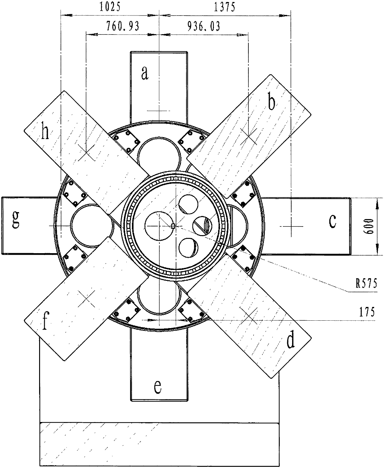
[0029] In one embodiment of the present invention, two eccentric wheels (9) are provided, and the two ends of one eccentric wheel (9) are adjacent to the keyway plate (30), and the periphery is surrounded by two concave sliders (16). 4 counterweights (29) and 2 eccentric wheels (9) surround 4 concave sliders (16) to form 8 center of gravity points around the fixed shaft (12). In this machine, the eccentric wheels (9) the diameter of outer circumference is 1150 millimeters, and the eccentricity of eccentric wheel (9) is 175 millimeters, like this, has just formed such as figure 1 The distance from the center of gravity of the 8 counterweights (29) to the centers of the spokes (4) is set to 2000 kg at the center of gravity of each counterweight (29), and each counterweight (29) center of gravity passes through the slide block The moment that guide frame (3) forms to wheel spoke (4) is:
[0030] a.0×2000=0
[0031] b.0.93603×2000=1872.06 kilograms of rice
[0032] c.1.375×2000=2750 kilograms of rice
[0033] d.0.93603×2000=1872.06 kilograms of rice
[0034] e.0×2000=0
[0035] f.-0.76093×2000=1521.86 kilograms of rice
[0036] g.-1.025×2000=2050 kilograms of rice
[0037] h.-0.76093×2000=1521.86 kilograms of rice
[0038] Above-mentioned 8 moment values are added up, and the moment sum that obtains each balance weight (29) center of gravity to wheel spoke (4) is: 1400 kilograms of meters, is according to the balance condition of fixed rotating shaft: positive and negative moment sum equals zero this According to the law, the torque of 1400 kgm will cause the spoke (4) to lose balance, resulting in clockwise rotation. During the rotation of the spoke (4), due to the existence of the eccentric wheel (9), the three positions of b, c, and d The concave slider (16) will move to the right, and continue to form a clockwise torque. Utilizing the 1400 kg torque of the spoke (4), it can be connected with the transmission and the generator through the coupling (6). After the generator is connected, the generator is driven to generate electricity.