
Parking brake

A parking brake and brake bottom plate technology, applied in the direction of brake types, brake components, brake actuators, etc., can solve the problems of critical driving safety, difficult operation of the driver, long stroke of the parking handle, etc., to ensure driving safety performance, saving internal space, and improving transmission efficiency

Pending Publication Date: 2019-09-17
霸州市华诚汽车制动器有限公司
View PDF0 Cites 0 Cited by
  • Summary
  • Abstract
  • Description
  • Claims
  • Application Information

AI Technical Summary

Problems solved by technology

[0002] At present, most of the brakes are built-in cables, and the transmission efficiency of the cables is in the range of 55%-70%. The efficiency is low, resulting in increased parking handle force and difficult operation by the driver.
At present, the self-energizing structure brake clearance adjustment structure is divided into two types: 1. Manual adjustment device, relying on manual adjustment, which cannot adjust the wear gap of the friction plate in time, resulting in long brake strokes, long strokes of the parking handle, and slow braking. Issues such as softness, endangering driving safety
2. Automatic reversing adjustment device, due to the driving direction of the car, the forward frequency is far greater than the number of reversing times, so the automatic adjustment device cannot completely compensate for the braking gap caused by the wear of the friction plate; and the automatic reversing adjustment device mainly relies on steel wires Completed, the automatic adjustment function is basically satisfied at the initial stage of braking, but after long-term use, the steel wire has insufficient lubrication and elongation, which leads to the gradual failure of the automatic adjustment function

Method used


Image

  • Parking brake
  • Parking brake
  • Parking brake

Examples


Embodiment Construction

[0018] The present invention will be further described in detail below in conjunction with the accompanying drawings and specific embodiments.

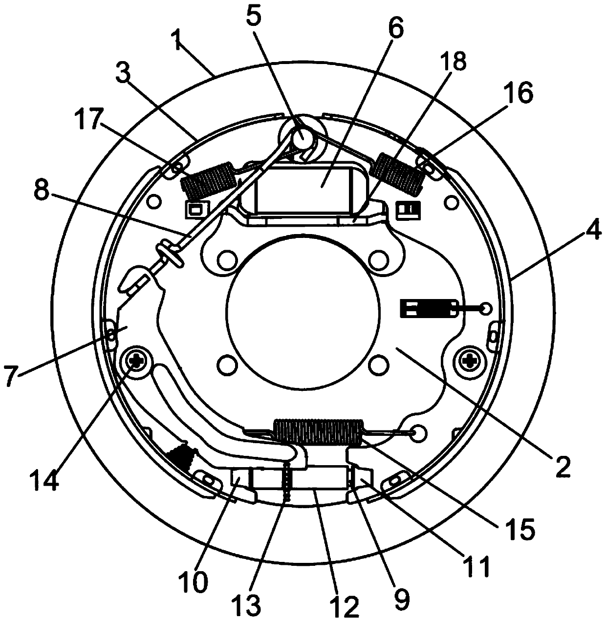
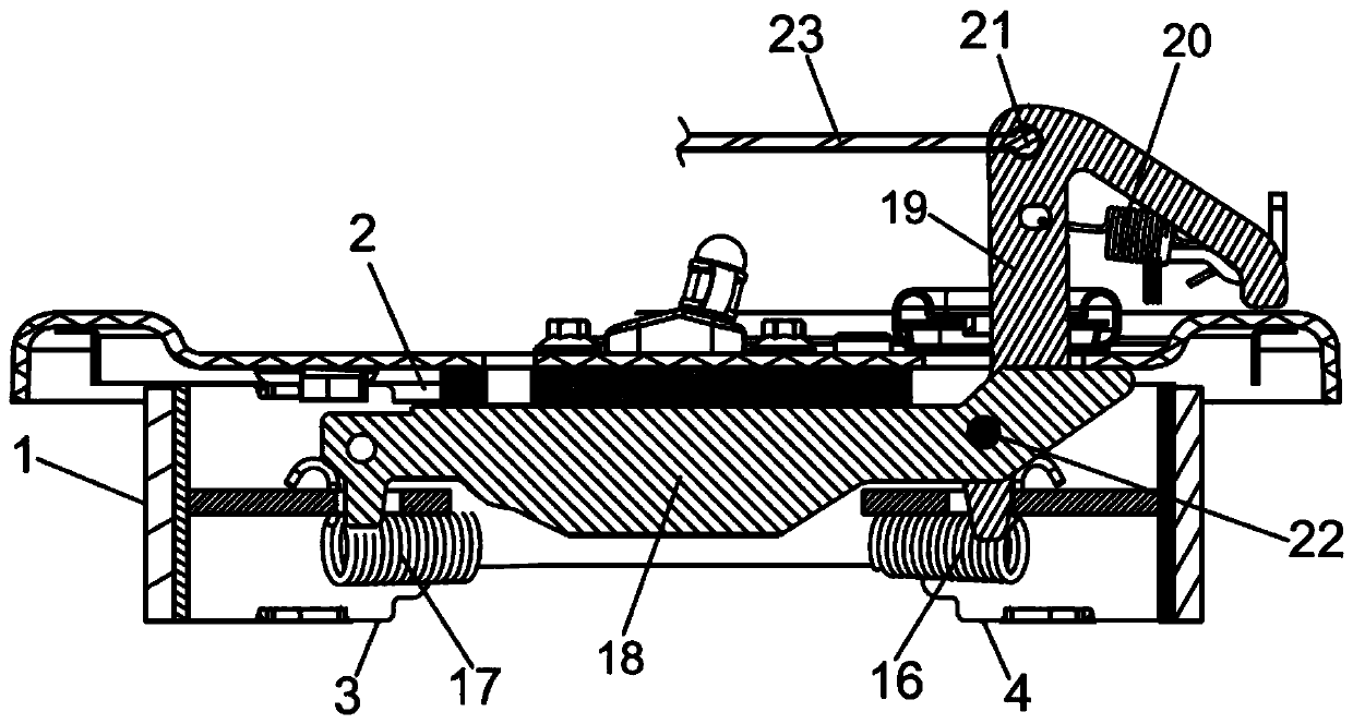
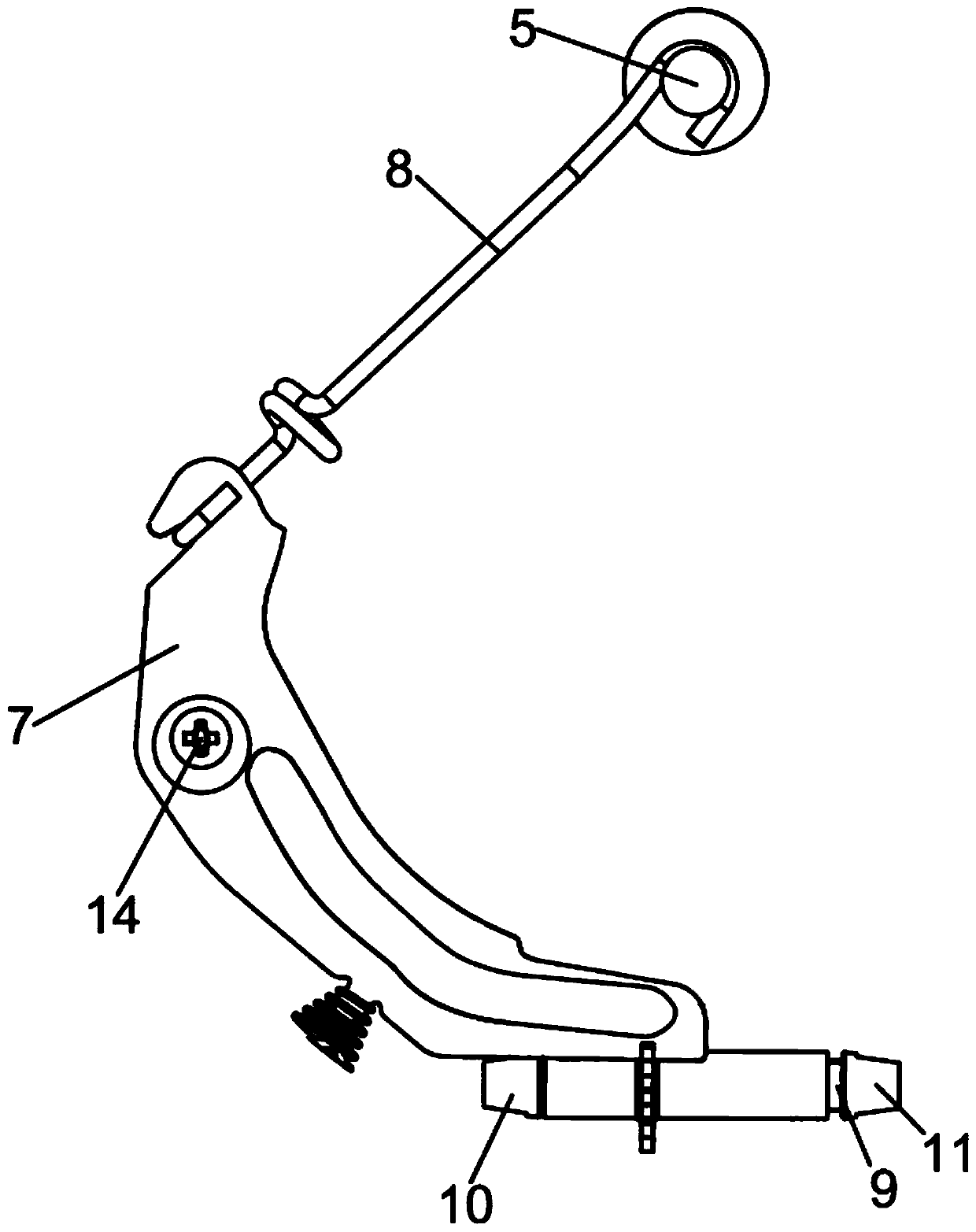
[0019] Depend on Figure 1-5It can be known from the illustrated embodiment that this embodiment includes a parking motion mechanism and a brake device, the brake device includes a brake drum 1 with an inner circular friction surface, the brake leading shoe 3 and the brake slave shoe 4 are arranged symmetrically from left to right On the brake bottom plate 2, so that the arc-shaped friction plates of the brake leading shoe 3 and the brake slave shoe 4 correspond to the inner circular friction surface of the brake drum 1, the brake leading shoe 3 and the brake slave shoe 4 The position between the corresponding upper ends is provided with a support pin 5, and the support pin 5 is fixed on the brake base plate 2. The parking motion mechanism includes a push plate 18, a brake pull arm 19, a pull arm return spring 20 and a brake pull. Th...


PUM


Abstract

The invention discloses a parking brake and belongs to the technical field of automobile braking. The parking brake comprises a parking movement mechanism and a brake device; the parking movement mechanism comprises a push plate, a brake pull arm, a pull arm return spring and a brake cable mounting hole; the brake device is further provided with a friction plate abrasion gap compensation mechanism; a ratchet wheel sleeve comprises a sleeve; a ratchet wheel is arranged in the circumferential direction of the sleeve; a sliding fit connecting hole of a brake leading shoe connector is arranged on the left side of an inner cavity of the sleeve; an inner threaded hole is formed in the right side of the inner cavity of the sleeve; a gap adjusting screw rod is in threaded connection with the inner threaded hole in the right side of the inner cavity of the sleeve; the right end of the gap adjusting screw rod is fixedly connected with the left end of a brake trailing shoe connecting piece; the left end of the brake leading shoe connector is provided with a connecting structure connected with the lower end of a brake leading shoe; and the right end of the brake leading shoe connector is in sliding fit connection with the sliding fit connecting hole of the brake leading shoe connector in the left side of the inner cavity of the sleeve. The parking brake has the characteristics of high cable transmission efficiency, safety, reliability, timely and accurate adjustment of the abrasion gap of a friction plate and the like.

Description

technical field [0001] The invention relates to the technical field of automobile braking. Background technique [0002] At present, most of the brakes are built-in cables, and the transmission efficiency of the cables is in the range of 55%-70%. The efficiency is low, resulting in increased parking handle force and difficult operation by the driver. At present, the self-energizing structure brake clearance adjustment structure is divided into two types: 1. Manual adjustment device, relying on manual adjustment, which cannot adjust the wear gap of the friction plate in time, resulting in long brake strokes, long strokes of the parking handle, and slow braking. Problems such as softness will endanger driving safety. 2. Automatic reversing adjustment device, due to the driving direction of the car, the forward frequency is far greater than the number of reversing times, so the automatic adjustment device cannot completely compensate for the braking gap caused by the wear of t...

Claims


Application Information

Patent Timeline
Patent Type & Authority Applications(China)
IPC IPC(8): F16H63/34F16D65/56F16D65/14F16D121/02F16D125/60F16D125/68
CPCF16H63/345F16H63/3483F16D65/14F16D65/561F16D2125/60F16D2125/68F16D2121/02
Inventor 颜培亮
Owner 霸州市华诚汽车制动器有限公司
Learn More