Bidirectional throttle valve

A two-way throttling valve and throttling technology, which is applied in the direction of safety valves, balance valves, valve devices, etc., can solve problems such as the two-way flow of throttle valves is not smooth, and achieve the effects of reducing structure, ensuring stability, and improving reaction speed

Active Publication Date: 2019-09-17
ZHEJIANG DUNAN MASCH CO LTD
View PDF9 Cites 5 Cited by
  • Summary
  • Abstract
  • Description
  • Claims
  • Application Information

AI Technical Summary

Problems solved by technology

[0003] Aiming at the deficiencies of the prior art, the present invention discloses a two-way throttle valve, which can solve the problem that the two-way flow of the existing throttle valve is not smooth

Method used


Image

  • Bidirectional throttle valve
  • Bidirectional throttle valve
  • Bidirectional throttle valve

Examples


Embodiment 1

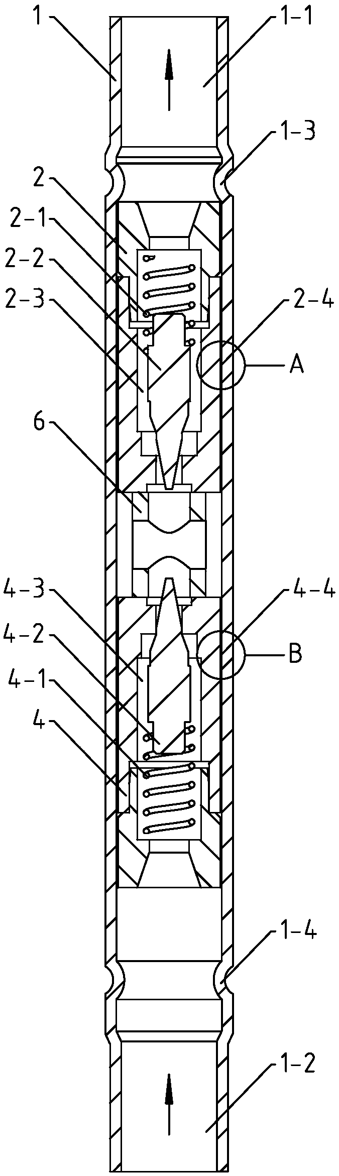
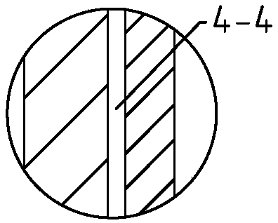
[0039] A two-way throttle valve described in the embodiment of the present invention, such as figure 1 As shown, it includes a valve pipe 1, a first valve body 2 and a second valve body 4 arranged in the valve pipe 1, the first valve body 2 is provided with a first throttling passage 2-3, and the first throttling passage 2- 3 is installed with the first valve needle 2-2 and the first spring 2-1, the first spring 2-1 pushes the first valve needle 2-2 to move in the direction of closing the first throttle passage 2-3, correspondingly, The second valve body 4 is provided with a second throttling passage 4-3, and a second valve needle 4-2 and a second spring 4-1 are installed in the second throttling passage 4-3, and the second spring 4-2 pushes the first The second valve needle 4-2 moves toward the direction of closing the second throttling passage 4-3. Such as figure 2 As shown, a first guide channel 2-4 is formed between the first valve body 2 and the valve tube 1, as imag...

Embodiment 2

[0048] The difference between the embodiment of the present invention and embodiment 1 is that, as Image 6 As shown, the first guide channel 2-4 spirally extends along the axial direction of the first valve body 2 on the outer wall of the first valve body 2. When the first valve body 2 is in the second throttling position, the medium passes through the first guide The channel 2-4, through the helically extended first guide channel 2-4, can make the medium generate an axial force on the first valve body 2 when passing through the first guide channel 2-4, so that the first valve body 2 is more stable in the second throttle position and will not move easily. It can be understood that the second guide passage 4-4 can also extend spirally along the axial direction of the second valve body 4 on the outer wall of the second valve body 4, and when the second valve body 4 is in the first throttling position, the medium passes through the second valve body 4. The second guide passage ...

Embodiment 3

[0054] Such as Figure 7 As shown, the difference between the embodiment of the present invention and embodiment 1 is that the first flow guide channel 2-4 and the second flow guide channel 4-4 are located on the inner wall of the valve tube 1, and the first flow guide channel 2-4 and the second flow guide channel The channel 4 - 4 extends helically along the axial direction of the valve tube 1 . The first guide channel 2-4 and the second guide channel 4-4 are directly formed on the inner wall of the valve tube 1, which is convenient for production and processing, and improves the versatility of the first valve body 2 and the second valve body 4, which is convenient for replacement and maintenance , thereby reducing costs.

[0055] Such as Figure 14 As shown, the bracket 6 can be located on the end of the second valve body 4 facing the first valve body 2 . The bracket 6 is provided with a radial communication groove 9-1 and an axial communication hole 9-3, the radial commu...


PUM


Abstract

The invention discloses a bidirectional throttle valve and relates to the technical field of throttle valves. The bidirectional throttle valve comprises a valve tube, and a first valve body and a second valve body arranged in the valve tube, wherein the valve tube is provided with a first interface and a second interface; the first valve body is provided with a first throttling channel; the second valve body is provided with a second throttling channel; and an intermediate communication channel is arranged between the first valve body and the second valve body in the valve tube. The bidirectional throttle valve is characterized in that a first diversion channel is arranged in the valve tube and between the first interface and the intermediate communication channel, a second diversion channel is arranged between the second interface and the intermediate communication channel, and the first valve body and the second valve body move synchronously in the axial direction of the valve tube. The bidirectional throttle valve can effectively realize the bidirectional flow control of the throttle valve.

Description

technical field [0001] The invention relates to the technical field of throttle valves, in particular to a two-way throttle valve. Background technique [0002] A throttling device is required in the refrigeration cycle system of a refrigeration device, and capillary throttling is often used as a throttling device, or an electronic expansion valve is used as a throttling device. Most of the existing throttling devices are throttling valves whose valve opening changes according to the pressure difference between the pressure of the refrigerant on the condenser side (primary side) and the pressure of the refrigerant on the evaporator side (secondary side). There is a spring that urges the valve needle in the valve closing direction against the force caused by the differential pressure. Existing valve throttling devices are prone to jamming during use, and there is no flow when fully closed or low pressure, and bidirectional flow cannot be realized or bidirectional flow is not...

Claims


Application Information

Patent Timeline
Patent Type & Authority Applications(China)
IPC IPC(8): F16K17/30F25B41/06F25B41/30
CPCF16K17/30F25B41/30
Inventor 单宇宽朱龙健金锯
Owner ZHEJIANG DUNAN MASCH CO LTD
Why Eureka
Try Eureka