Visible light heat reflection temperature measuring device

A temperature measurement device and heat reflection technology, which can be used in measurement devices, Raman scattering, material analysis by optical means, etc., can solve problems such as difficult to achieve, and achieve the effects of reducing measurement errors, improving time resolution, and clearing images.

Active Publication Date: 2019-09-17
INST OF ELECTRICAL ENG CHINESE ACAD OF SCI
View PDF10 Cites 6 Cited by
  • Summary
  • Abstract
  • Description
  • Claims
  • Application Information

AI Technical Summary

Problems solved by technology

Because capturing an image with a sufficiently high time resolution requires the pulse width of the illumination source to be at the level of microseconds or even nanoseconds, and it is also necessary to adapt the exposure time of the CCD cam

Method used


Image

  • Visible light heat reflection temperature measuring device
  • Visible light heat reflection temperature measuring device
  • Visible light heat reflection temperature measuring device

Examples


Embodiment Construction

[0026] The technical solutions of the present invention will be clearly and completely described below in conjunction with the accompanying drawings. Apparently, the described embodiments are some of the embodiments of the present invention, but not all of them. Based on the embodiments of the present invention, all other embodiments obtained by persons of ordinary skill in the art without making creative efforts belong to the protection scope of the present invention.

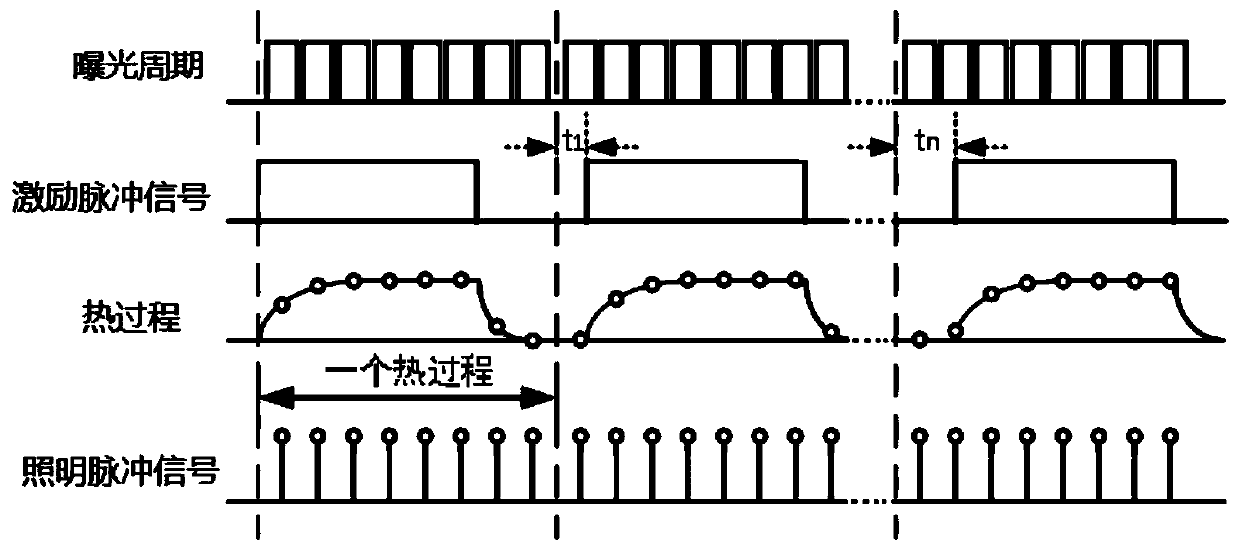
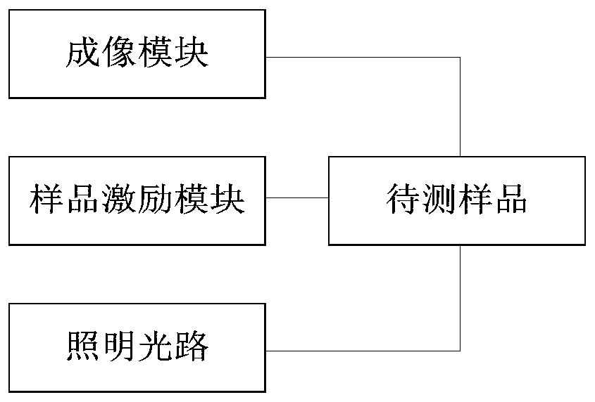
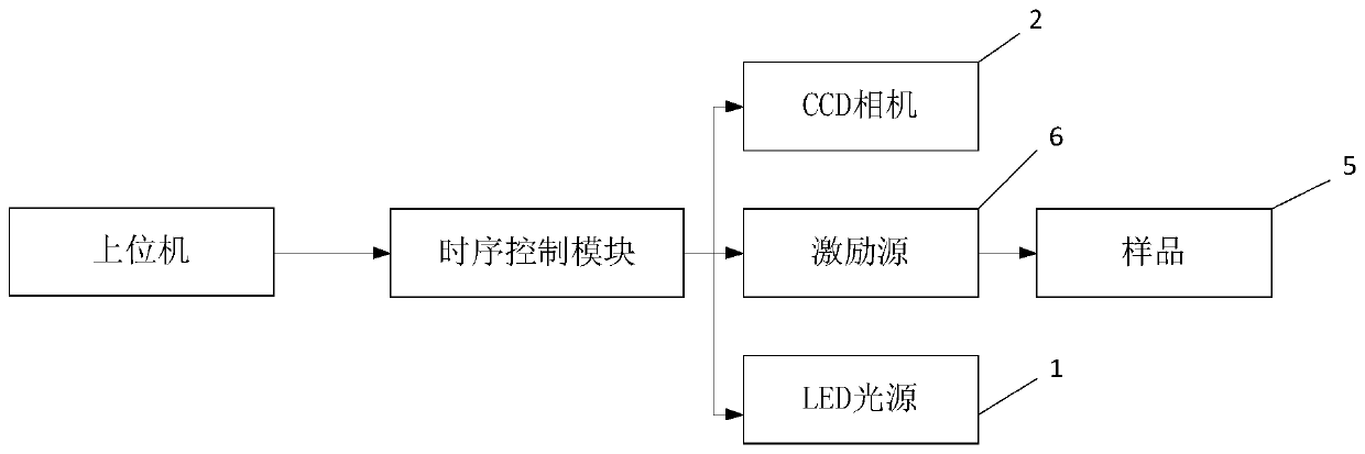
[0027] Embodiments of the present invention provide a visible light heat reflection temperature measuring device, such as figure 2 , image 3 and Figure 5 , the device includes: a manipulation module, a timing control module, an imaging module 2 , an illumination optical path 3 and a sample excitation module 6 .

[0028] The control module is used to set timing synchronization parameters and send start commands; the timing control module performs synchronous timing control on the imaging module 2, the exci...


PUM


Abstract

The invention discloses a visible light heat reflection temperature measuring device. The device comprises an illumination light path used for providing an illumination pulse signal for a to-be-measured sample, a sample excitation module used for applying excitation pulse signals to the to-be-measured sample, an imaging module used for capturing illumination pulse reflection signals reflected by the to-be-measured sample and acquiring a thermal process image of the to-be-measured sample under the excitation of the excitation pulse signals, wherein the imaging module captures the illumination pulse reflection signals corresponding to the same phases of the excitation pulse signals within the same exposure period; and the phases of the excitation pulse signals corresponding to the illumination pulse reflection signals captured by the imaging module in different exposure periods are different. The thermal process image of a semiconductor device can be realized through the visible light thermal reflection temperature measuring device; and the preset duration is shortened, and the preset phase difference between the illumination pulse signals and the excitation pulse signals is reduced, so that the time precision of the thermal imaging process is improved, and the time resolution is greatly improved.

Description

technical field [0001] The invention relates to the technical field of microscopic imaging, in particular to a visible light heat reflection temperature measuring device. Background technique [0002] In the field of semiconductor devices, first of all, due to the continuous breakthrough of micro-nano processing technology, the number of transistors per unit area is increasing, which has reached billions per square centimeter, and the operating frequency of electronic devices is getting higher and higher. It has reached GHz; secondly, due to the frequent switching action of semiconductor devices in the working process, it will cause heat generation, which will cause the temperature inside the device to rise, and temperature is a crucial parameter of semiconductor integrated circuits. An important basis for the failure mechanism, so a thermal distribution measurement technique with high temporal and spatial resolution is required. [0003] However, there are three commonly u...

Claims


Application Information

Patent Timeline
IPC IPC(8): G01N21/01G01N21/63G01N21/65
CPCG01N21/01G01N21/63G01N21/65
Inventor 王大正刘珠明郑利兵司维康
Owner INST OF ELECTRICAL ENG CHINESE ACAD OF SCI
Why Eureka
Try Eureka