A 1pps Pulse Signal Timing Method

A technology of pulse signal and time correction, applied to radio-controlled timers, instruments, etc., can solve problems such as insufficiency, and achieve the effect of increasing time accuracy and eliminating travel time errors

Inactive Publication Date: 2021-04-13
KUNMING UNIV OF SCI & TECH
View PDF19 Cites 0 Cited by
  • Summary
  • Abstract
  • Description
  • Claims
  • Application Information

AI Technical Summary

Problems solved by technology

The accuracy that can be achieved by using this long wave as a time synchronization technology has entered the microsecond level, but because the accuracy of the system and the range it can cover are very limited, this is far from the need for further development of production and research. not enough

Method used


Image

  • A 1pps Pulse Signal Timing Method
  • A 1pps Pulse Signal Timing Method
  • A 1pps Pulse Signal Timing Method

Examples


Embodiment 1

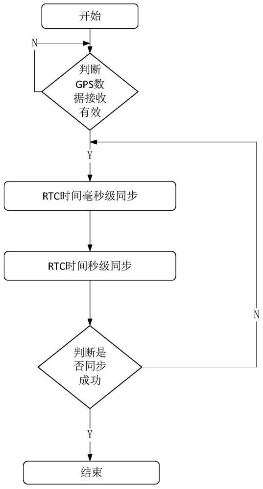
[0023] Embodiment 1: as attached Figure 1-5 Shown, a kind of 1pps pulse signal timing method, the concrete steps of described method are as follows:

[0024] Step1, first determine whether the GPS data reception is valid: through the special sentence in the NMEA-0183 protocol about whether the GPS data positioning is successful or not;

[0025] Step2. Determine whether the 1pps pulse exists: observe whether the 1pps pulse is input and valid through the oscilloscope display, if so, it means that the 1pps pulse exists, otherwise, it means that the 1pps pulse does not exist;

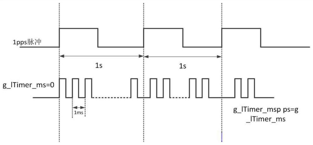
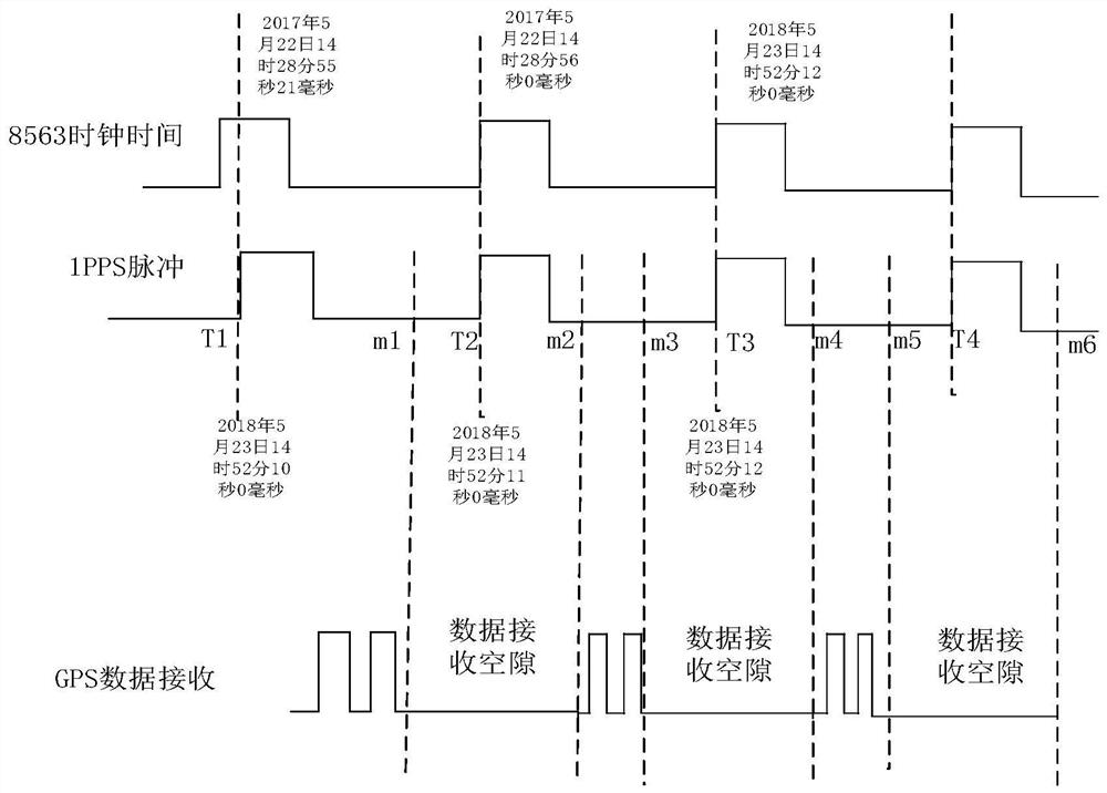
[0026] Step3. Perform millisecond-level synchronization of RTC time: when the rising edge of the 1pps pulse arrives, it is considered to be UTC time at this time, and the timing starts at a rising edge of the 1pps pulse. At this time, the rising edge of the 1pps pulse is used to perform milliseconds on the system clock time The level is cleared to realize the synchronization of the system clock at the mil...


PUM


Abstract

The invention relates to a 1pps pulse signal timing method and belongs to the technical field of wireless communication networks. The present invention mainly realizes the high-precision timing function of NMEA‑0183+1pps on the STM32F407 platform. In the synchronous system, the 1pps pulse (1 PULSE PER SECOND one pulse output per second) is mainly used. This pulse is a standard TTL logic output form. When the navigation output is valid, the rising edge of the pulse corresponds to the time. The function of the 1pps pulse here is to use its rising edge as the UTC time synchronization signal, and then realize time synchronization by analyzing the NMEA‑0183 protocol.

Description

technical field [0001] The invention relates to a 1pps pulse signal timing method and belongs to the technical field of wireless communication networks. Background technique [0002] Clocks are usually designed for low cost, and keeping accurate time becomes secondary. Even reasonably accurate computer clocks can be damaged by manufacturing defects, temperature changes, electromagnetic interference, the age of the quartz crystal, or even changes in system load. And change. Furthermore, even with a time system with a small error, the error can increase significantly over a long period of time. [0003] In the early 20th century, the United States implemented short-wave radio broadcasting for the first time. After continuous experiments, the problem of time synchronization in most areas was finally solved, and the accuracy continued to break through. Now it has reached the millisecond level. In the ensuing decades, the primary means of time synchronization has remained uncha...

Claims


Application Information

Patent Timeline
Patent Type & Authority Patents(China)
IPC IPC(8): G04R20/02
CPCG04R20/02
Inventor 彭艺刘煜恒
Owner KUNMING UNIV OF SCI & TECH
Why Eureka
Try Eureka