
Rotary type permanent magnet electrodynamic suspension and driving integrated testing device

A test device, electric suspension technology, applied in the direction of measuring device, measurement using suspension technology, magnetic performance measurement, etc., can solve the problems of high cost, complex structure design, difficult maintenance, etc., and achieve low cost, high degree of visualization, and easy operation convenient effect

Pending Publication Date: 2019-09-17
SOUTHWEST JIAOTONG UNIV
View PDF0 Cites 9 Cited by
  • Summary
  • Abstract
  • Description
  • Claims
  • Application Information

AI Technical Summary

Problems solved by technology

However, the static levitation device disclosed in this proposal has the following technical problems: 1) It adopts a semi-cylindrical wrapped track guide groove structure, which is not conducive to track heat dissipation, and a refrigeration system needs to be installed, which increases the deadweight and cost of the system
2) The device is driven by a double-shaft extension motor, which has high noise and power, and the motor generates serious heat
3) The inherent magnetic resistance of electric levitation is not used, and a linear motor needs to be installed independently to drive; 4) This device is only suitable for maglev trains
However, the coil type permanent magnet electric levitation device disclosed in this scheme has the following technical problems: 1) The design of the wrapping structure of the linear double Halbach permanent magnet array is complicated, the space utilization rate of the car body is low, and it is not easy to maintain
2) The device cannot achieve static suspension, and the eddy current loss requires high processing accuracy of the coil
3) The device adopts a zero-flux coil structure and needs to be laid along the line, which is difficult to design and high in cost
4) This device is only suitable for maglev trains

Method used


Image

  • Rotary type permanent magnet electrodynamic suspension and driving integrated testing device
  • Rotary type permanent magnet electrodynamic suspension and driving integrated testing device
  • Rotary type permanent magnet electrodynamic suspension and driving integrated testing device

Examples


Embodiment Construction

[0031] In order to make the object, technical solution and advantages of the present invention clearer, the present invention will be further described in detail below in conjunction with the accompanying drawings and embodiments. It should be understood that the specific embodiments described here are only used to explain the present invention, not to limit the present invention.

[0032] On the contrary, the invention covers any alternatives, modifications, equivalent methods and schemes within the spirit and scope of the invention as defined by the claims. Further, in order to make the public have a better understanding of the present invention, some specific details are described in detail in the detailed description of the present invention below. The present invention can be fully understood by those skilled in the art without the description of these detailed parts.

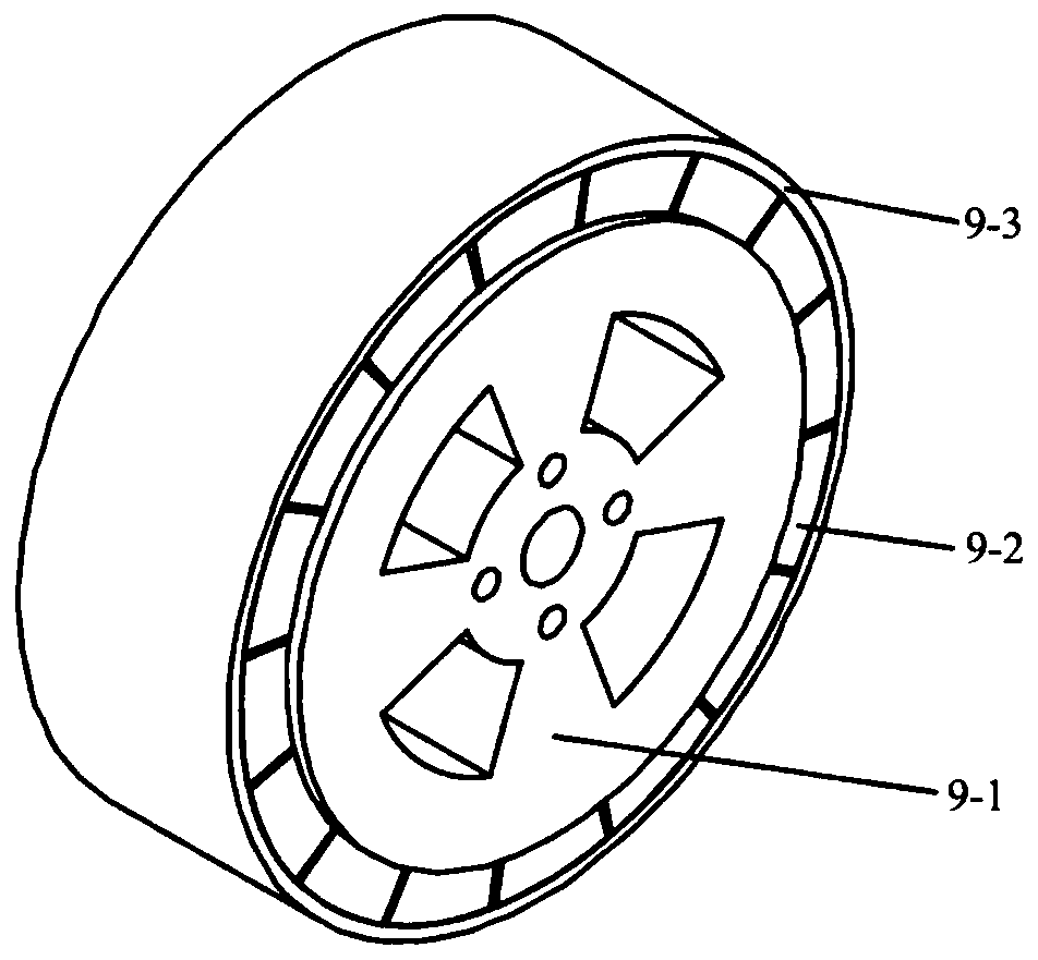
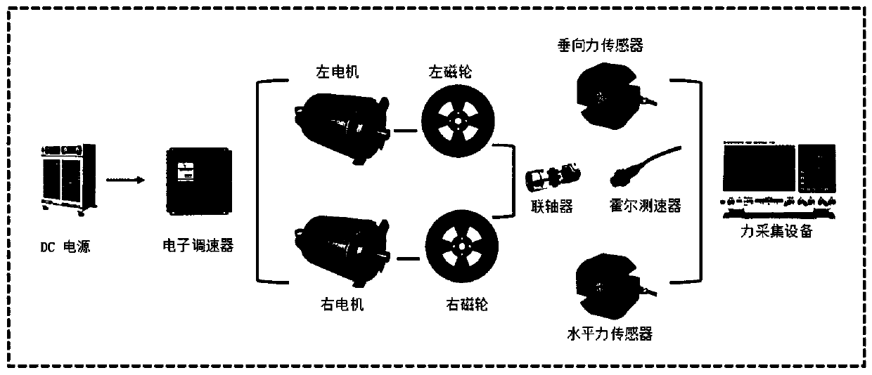
[0033] Such as figure 1 As shown, the embodiment of the present invention provides a rotary permanent...


PUM

PropertyMeasurementUnit
thicknessaaaaaaaaaa
thicknessaaaaaaaaaa

Abstract

The invention belongs to the technical field of permanent magnet electrodynamic type magnetic suspension and particularly relates to a rotary type permanent magnet electrodynamic suspension and driving integrated testing device. The testing device comprises a suspension body, a suspension body motion support allowing the suspension body to move in a vertical dimension and a horizontal dimension, and a suspension force and driving force acquisition unit; an annular Halbach permanent magnet array is adopted, and the electrodynamic suspension inherent magnetic resistance is ingeniously converted into the driving force of the device by means of mechanical rotational motion; a support for two-dimensional motion of the suspension body is built through a sliding assembly, so that free motion of the device in the vertical direction and the horizontal direction can be realized, that is, a suspension-driving integrated demonstration and force acquisition function is met; dynamic suspension and data acquisition of the suspension force, the driving force and the like under different suspension heights and different rotating speeds can be realized, the testing device can be used as an electrodynamic suspension force characteristic research platform, the manufacturing cost is low, and the operation is convenient and fast.

Description

technical field [0001] The invention belongs to the technical field of permanent magnet electric magnetic levitation, and in particular relates to a rotating permanent magnet electric levitation and driving integrated test device. Background technique [0002] The existing permanent magnet electric levitation technology is mainly used in maglev trains, and its technical principle is based on the evolution of the traditional plate permanent magnet electric levitation structure. [0003] A static levitation device (CN2015106009945) disclosed in the prior art for permanent magnet electric maglev trains, including a bogie installed on the maglev train, a cylindrical permanent magnet composite structure, and a cylindrical permanent magnet module. Semi-cylindrical grooved guide rail. The four cylindrical permanent magnet structures on the device are distributed in pairs on both sides of the bogie, and each side is equipped with a double-shaft extension motor to drive the cylindri...

Claims


Application Information

Patent Timeline
Patent Type & Authority Applications(China)
IPC IPC(8): G01R33/12G01L5/00
CPCG01R33/1261G01L5/00
Inventor 邓自刚张帅金利安张泽赵景忠桑晓晨
Owner SOUTHWEST JIAOTONG UNIV
Features
  • Generate Ideas
  • Intellectual Property
  • Life Sciences
  • Materials
  • Tech Scout
  • Unparalleled Data Quality
  • Higher Quality Content
  • 60% Fewer Hallucinations
Learn More