A Short Magnetic Circuit Switched Reluctance Motor Generating Axial Force

A technology of switched reluctance motor and short magnetic circuit, which is applied in the direction of static parts of magnetic circuit, rotating parts of magnetic circuit, shape/style/structure of magnetic circuit, etc. Low efficiency and other problems, to achieve the effect of short magnetic circuit, improved performance, and improved work efficiency

Inactive Publication Date: 2016-08-24
JIANGSU UNIV
View PDF6 Cites 0 Cited by
  • Summary
  • Abstract
  • Description
  • Claims
  • Application Information

AI Technical Summary

Problems solved by technology

[0004] Aiming at the problems of long effective magnetic circuit, low motor efficiency and heavy weight in existing switched reluctance motors, the present invention proposes a switched reluctance motor structure with a short magnetic circuit that generates axial force, which effectively reduces the overall quality of the motor and realizes The circulation of the short magnetic circuit reduces the iron loss generated when the magnetic circuit circulates in the stator and rotor core, and improves the working efficiency of the motor

Method used


Image

  • A Short Magnetic Circuit Switched Reluctance Motor Generating Axial Force
  • A Short Magnetic Circuit Switched Reluctance Motor Generating Axial Force
  • A Short Magnetic Circuit Switched Reluctance Motor Generating Axial Force

Examples


Embodiment Construction

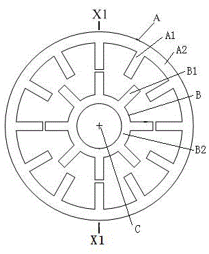
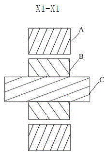
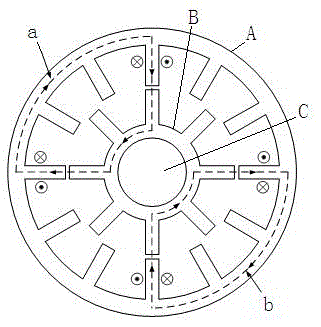
[0024] A short magnetic circuit switched reluctance motor generating axial force in the present invention is illustrated by taking a 6 / 4 switched reluctance motor as an example. Such as Figure 4 , 5 , 6, the present invention includes a motor casing 1, a stator tooth pole, a rotor tooth pole and a rotating shaft 13. The outermost part is the motor casing 1. On the inner wall of the motor casing 1, the stator teeth 2, 3, 4, 5, 6, 7 are evenly distributed along the circumferential direction of the radial section, and all the stator teeth are fixed on the motor casing 1. On the inner wall; a sleeve 12 is fixed outside the rotating shaft 13, and the outer wall of the sleeve 12 is uniformly distributed on the rotor tooth poles 8, 9, 10, 11 along the circumferential direction of the radial section, and all the rotor tooth poles 8, 9, 10, 11 They are all fixed on the outer wall of the sleeve 12, and there is a radial air gap between the stator tooth poles and the rotor tooth poles...


PUM


Abstract

The invention discloses a short magnetic circuit switch reluctance motor capable of generating axial force. A plurality of stator tooth electrodes are evenly distributed in the circumferential direction of the radial cross section on the inner wall of an motor outer shell. A sleeve is fixedly arranged on the outside of a rotating shaft in a sleeved mode, and a plurality of rotor tooth electrodes are evenly distributed in the circumferential direction of the radial cross section on the outer wall of the sleeve. The axial cross section of each stator tooth electrode is in a rectangle shape which is defined by four faces and is provided with an L-shaped notch, and each rotor tooth electrode is in an L shape defined by two vertical faces in the same axial cross section. Radial gas gaps are reserved between the radial ends of the rotor tooth electrodes and the radial ends of the stator tooth electrodes, axial gas gaps are reserved between the axial ends of the rotor tooth electrodes and the axial ends of the stator tooth electrodes, and the axial cross section shape of the stator tooth electrodes and the axial cross section shape of the rotor tooth electrodes define a complete rectangle shape with two gas gaps reserved. The structure of the stator tooth electrodes and the rotor tooth electrodes is changed to change magnetic circuits, circulating of the short magnetic circuits is achieved, and all kinds of performance of the motor is improved.

Description

technical field [0001] The invention belongs to the field of motors, in particular to a switched reluctance motor generating axial force. Background technique [0002] Switched reluctance motors have the advantages of simple and solid structure, simple manufacturing process, low cost, large starting torque, good low-speed performance and high efficiency, and can adapt to various harsh working environments, making switched reluctance motors widely used in aerospace, mining and other environments. It is widely used in harsh and safety demanding fields. [0003] The traditional switched reluctance motor is a doubly salient pole structure, such as figure 1 The radial structure of the switched reluctance motor with a 12 / 8 structure is shown. The switched reluctance motor consists of a stator A, a rotor B, and a rotating shaft C. The stator A is fixed on the inner wall of the motor casing, and the rotor B is coaxially fixed on the rotating shaft. On C, the stator A is coaxially ...

Claims


Application Information

Patent Timeline
Patent Type & Authority Patents(China)
IPC IPC(8): H02K1/14H02K1/18H02K1/24H02K1/28
Inventor 孙玉坤胡文宏朱志莹袁野张新华
Owner JIANGSU UNIV
Why Eureka
Try Eureka