Built-in shielded electrical penetration apparatus and system and installation method of system

An electrical penetration and built-in technology, applied in the direction of nuclear power generation, greenhouse gas reduction, climate sustainability, etc., can solve the problems of unreliable electrical and sealing performance, difficult cable replacement, etc., and achieve good radiation shielding performance and good shielding performance, ease of inspection and maintenance work

Pending Publication Date: 2019-09-17
NUCLEAR POWER INSTITUTE OF CHINA
View PDF0 Cites 0 Cited by
  • Summary
  • Abstract
  • Description
  • Claims
  • Application Information

AI Technical Summary

Problems solved by technology

[0007] The purpose of the present invention is to provide a built-in shielded electrical penetration device, which solves the problem of unreliable electrical and sealing performance and difficult cable replacement caused by the use of cable pipes dir

Method used


Image

  • Built-in shielded electrical penetration apparatus and system and installation method of system

Examples


Example Embodiment

[0049] [Example 1]

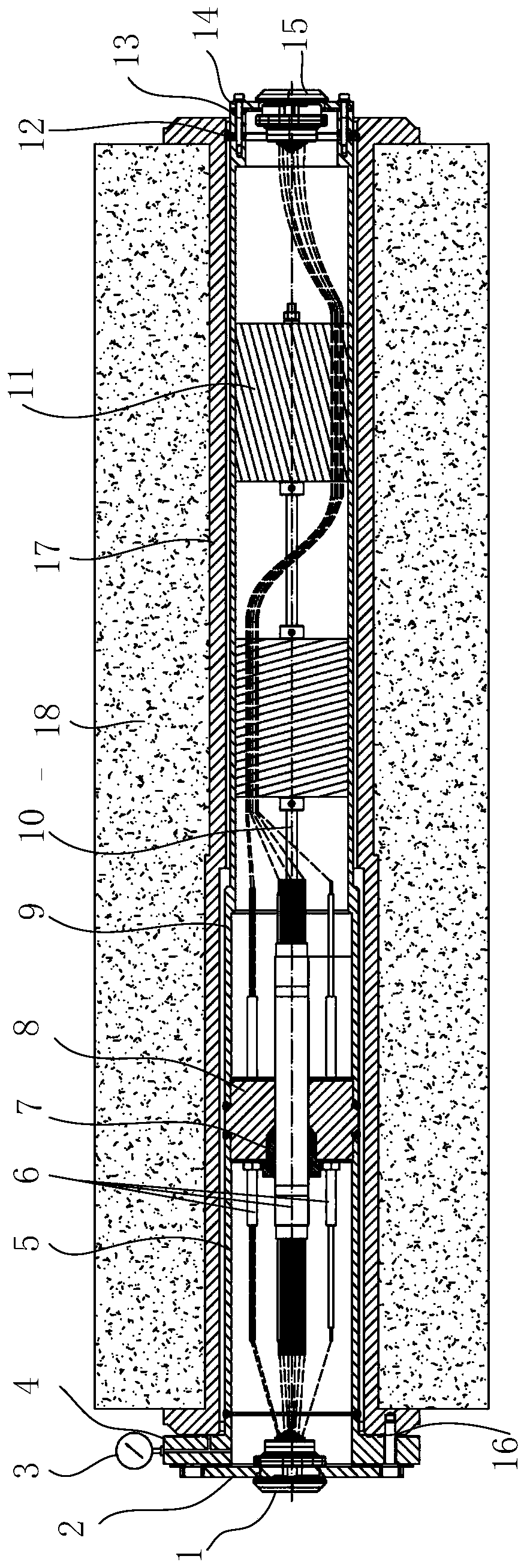
[0050] Such as figure 1 As shown, a built-in shielded electrical penetration system includes a pre-embedded bushing 17 arranged in a wall 18 and a built-in shielded electrical penetration device penetrating the embedded bushing 17, so A connecting flange is provided on the left side of the embedded sleeve 17, the left end surface of the connecting flange is used as the left end surface of the embedded sleeve 17, the left end of the electrical penetration device is provided with an end plate flange 4, the electrical penetration device The end plate flange 4 is connected to the left end surface of the embedded casing. Specifically, the connecting flange and the end plate flange 4 are installed by flange bolts; a seal is provided between the end plate flange 4 and the embedded casing 17 The sealing ring 16 is used to seal the gap between the end surface of the embedded sleeve 17 and the side surface of the end plate flange 4. Between the end plate flange 4 and...


PUM


Abstract

The invention discloses a built-in shielded electrical penetration apparatus and system and method. The apparatus comprises a conductor assembly, a cylinder assembly, a front zone side wiring apparatus, and a hot cell side wiring apparatus, wherein the cylinder assembly comprises a barrel body and end plate flanges, the barrel body comprises a hot cell side cylinder body, a fixing apparatus and a front zone side cylinder body, the front zone side wiring apparatus, the end plate flanges, the front zone side cylinder body, the fixing apparatus, and the hot cell side cylinder body are sequentially connected, a shielding assembly in the cylinder body is provided with a through hole or a concave groove through which the conductor assembly or extension wires of the conductor assembly passes, the conductor assembly is connected with the fixing apparatus in a sealing manner, and the conductor assembly or extension wires of two ends of the conductor assembly protrude from the fixing apparatus and pass through the shielding assembly and are connected or directly connected with connectors on two wiring apparatuses. The built-in shielded electrical penetration apparatus has high integration degree, a compact structure, excellent performance, and convenient maintenance and repair, and has good radiation protection function, excellent sealing and electrical performance and anti-shake performance, and thus good mechanical integrity and electrical integrity can be ensured.

Description

technical field [0001] The invention relates to electrical penetration technology in the nuclear field, in particular to an embedded electrical penetration device with shielding, a system and an installation method thereof. Background technique [0002] In the field of nuclear technology, a hot cell is a shielded small room for high-radioactivity tests and operations, which is isolated from the surrounding environment by the hot cell shell or shielded walls. At present, the hot cell cable usually uses a cable tube to directly penetrate the hot cell shell and the shielding wall, and partially seals the tube opening with a sealing filler. This way of cables running through the shielded wall of the hot cell has the following disadvantages: [0003] (1) Unreliable electrical and sealing performance. The sealing packing and the cable itself are easy to age, the sealing effect is poor, and the electrical and sealing performance cannot be guaranteed for a long time under harsh en...

Claims


Application Information

Patent Timeline
IPC IPC(8): G21C13/032G21C13/028G21C13/02
CPCG21C13/032G21C13/028G21C13/02Y02E30/30
Inventor 王新宇周天王江武王广金陈青周缘赵雨恒邱新媛
Owner NUCLEAR POWER INSTITUTE OF CHINA
Why Eureka
Try Eureka