Electroluminescent device, preparation method thereof and display device

A technology of electroluminescent devices and light-emitting units, which is applied in the direction of electric solid-state devices, semiconductor/solid-state device manufacturing, electrical components, etc. It can solve the problems of discounted water and oxygen barrier ability, device damage, insufficient interface affinity, etc., and achieve the change of total reflection Angle, improve service life, improve the effect of encapsulation

A technology of electroluminescent devices and light-emitting units, which is applied in the direction of electric solid-state devices, semiconductor/solid-state device manufacturing, electrical components, etc. It can solve the problems of discounted water and oxygen barrier ability, device damage, insufficient interface affinity, etc., and achieve the change of total reflection Angle, improve service life, improve the effect of encapsulation

CN110246985AActive Publication Date: 2019-09-17BOE TECH GRP CO LTD +1

Image

  • Electroluminescent device, preparation method thereof and display device
  • Electroluminescent device, preparation method thereof and display device
  • Electroluminescent device, preparation method thereof and display device

Examples


Embodiment Construction

[0027] Example embodiments will now be described more fully with reference to the accompanying drawings. Example embodiments may, however, be embodied in many forms and should not be construed as limited to the embodiments set forth herein; rather, these embodiments are provided so that this disclosure will be thorough and complete, and will fully convey the concept of example embodiments to those skilled in the art. In the drawings, the thickness of regions and layers are exaggerated for clarity. The same reference numerals in the drawings denote the same or similar structures, and thus their detailed descriptions will be omitted.

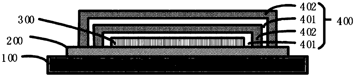
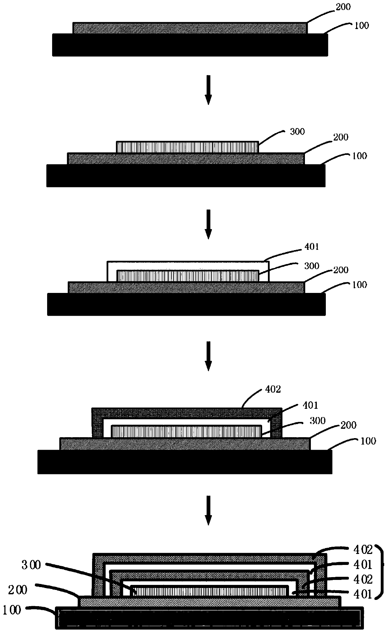
[0028] figure 1 A schematic diagram showing a transparent OLED device without a separated glass substrate as an embodiment of the present invention. like figure 1 As shown, the electroluminescent device is carried on a glass carrier substrate 100 , including a base substrate 200 , a light emitting unit 300 and an encapsulation layer 400 . The...


PUM

PropertyMeasurementUnit
particle diameteraaaaaaaaaa
thicknessaaaaaaaaaa
thicknessaaaaaaaaaa

Abstract

Provided is an electroluminescent device comprising: a substrate base plate; an illumination unit disposed on a surface of the substrate; and an encapsulation layer encapsulating the illumination unit; wherein the encapsulation layer comprises an inorganic encapsulation film alternately stacked and an organic-inorganic composite layer comprising methyl-modified nano-inorganic particles and a polymer material. The encapsulation structure of the flexible OLED provided by the invention has the characteristics of low cost, high resistance to water and oxygen, bending resistance, good flexibility, light enhancement effect, etc., and overcomes the shortcomings of high rigidity, high cost, easy damage and the like of the glass package and the inorganic film package.

Description

technical field [0001] The invention belongs to the field of display technology, and in particular relates to an electroluminescence device, a preparation method thereof and a display device. Background technique [0002] Flexible Organic Light-Emitting Diode (FOLED) has the advantages of self-luminous display, fast response, high brightness, and wide viewing angle. Moreover, FOLED is a display based on organic materials, without liquid filling, can be rolled, folded, and even worn, etc., which is a very good portable product. [0003] However, the current FOLEDs mostly use inorganic multilayer thin films (SiO x , SiN x ) for staggered stack packaging. However, the CVD film formation temperature of the inorganic film silicon nitride and silicon oxide is relatively high and will cause certain damage to the device and affect the performance of the device. Moreover, certain pinholes (pin holes) will be generated during the CVD process, which will affect the packaging effect...

Claims


Application Information

Patent Timeline
17 Sep 2019
Publication
CN110246985A
IPC
H01L51/52; H01L51/56; B82Y30/00
CPC
B82Y30/00; H10K50/8445; H10K50/854; H10K71/00
Inventors
李小宝; 宫奎