Heat radiation method for circulation electrical cabinet
A heat dissipation method and technology for electrical cabinets, which are applied to the cooling/ventilation of substations/switchgears, electrical components, and details of the layout of substations/switches, etc. Effect
- Summary
- Abstract
- Description
- Claims
- Application Information
AI Technical Summary
Problems solved by technology
Method used
Image

Examples
Embodiment 1
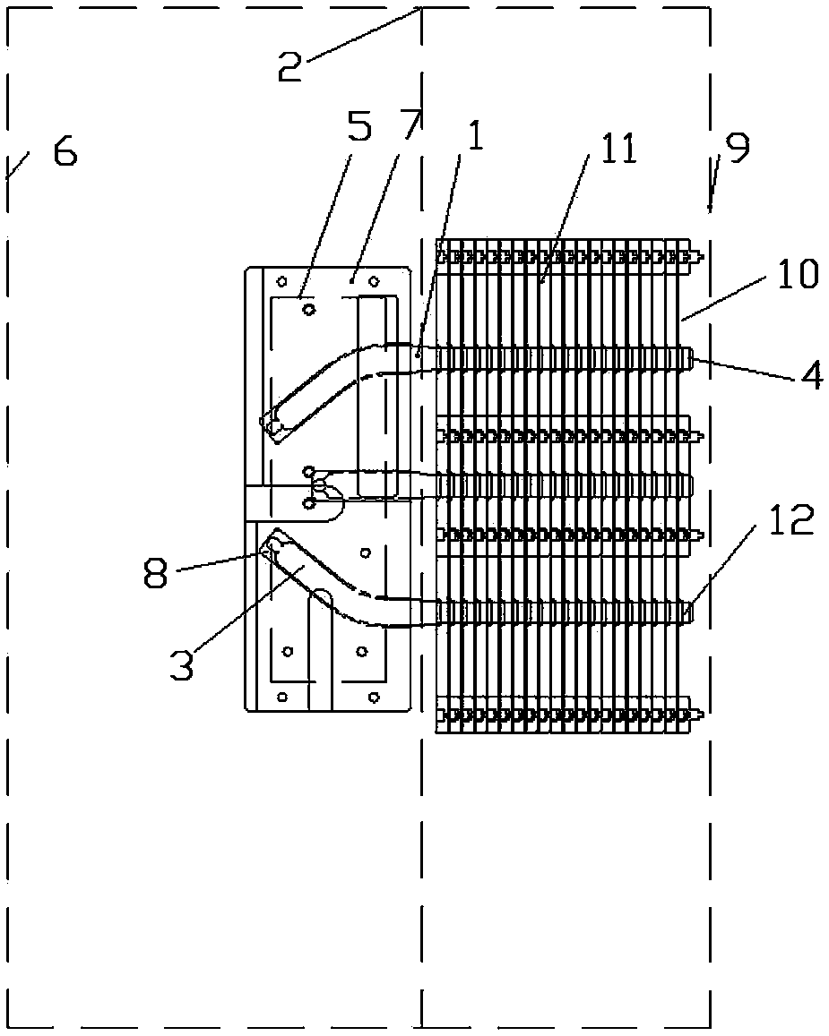
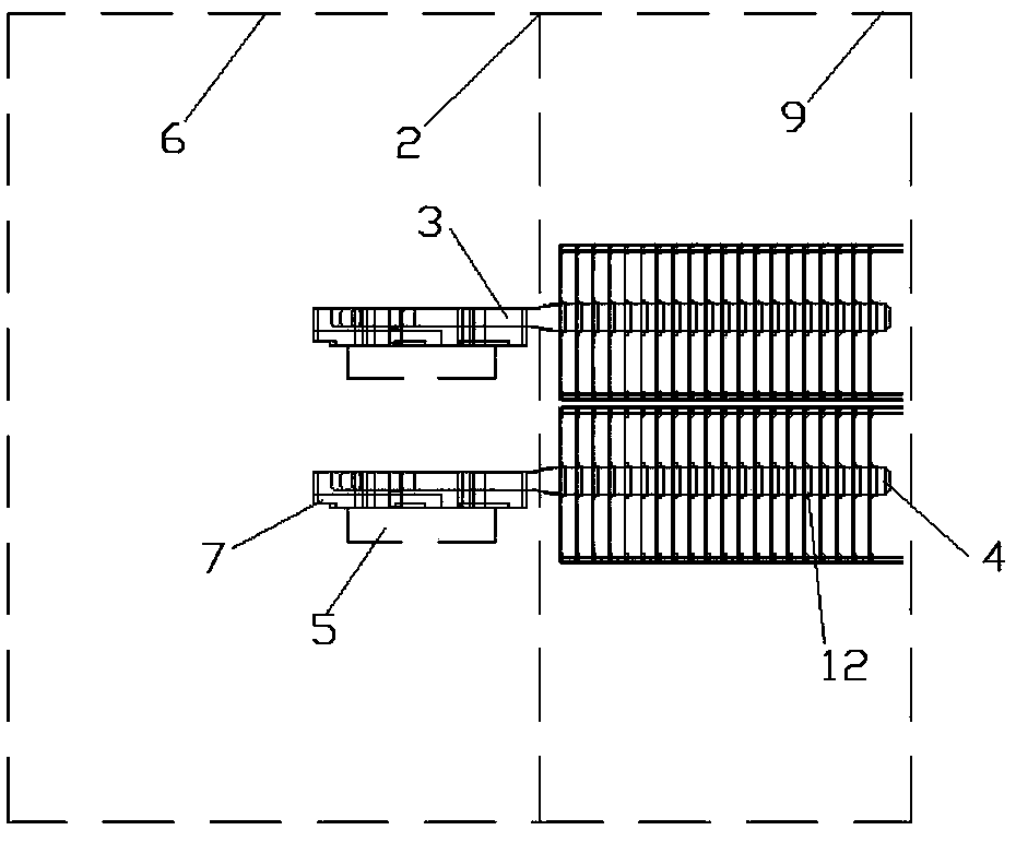
[0022] The heat dissipation method of the circulating electric cabinet adopts a plurality of heat pipes 1 to connect with the circulating electric cabinet 2, wherein: the evaporating section 3 of the heat pipe 1 extends into the inner circulation chamber 6 of the electric cabinet equipped with heat dissipation components 5 and is connected with the heat dissipation elements. The device 5 is connected, the condensation section 4 of the heat pipe 1 is located outside the inner circulation cavity 6 of the electric cabinet, the evaporation section 3 of the heat pipe 1 collects the heat generated by the work of the heat dissipation component 5, and transfers the collected heat to the circuit located in the electric cabinet. The condensation section 4 outside the circulation cavity 6 in the cabinet 2 dissipates heat to the atmospheric environment outside the circulation cabinet body 2 through the condensation section 4 of the heat pipe 1 . In this embodiment, a through hole is opened...
Embodiment 2
[0026] This embodiment is a further improvement on the basis of embodiment 1. Compared with embodiment 1, in this embodiment, the condensation section 4 of the heat pipe 1 passes through the inner circulation cavity 6 and has a through hole and is located in the electric cabinet. In the outer circulation chamber 9 of the electric cabinet, a heat dissipation terminal piece 10 is arranged in the outer circulation chamber 9 of the electric cabinet, and the condensation section 4 of the heat pipe 1 is fixedly connected with the heat dissipation terminal piece 10 . Wherein: the heat dissipation terminal piece 10 includes a plurality of fins 11 arranged in parallel, on the fins 11, there are turned holes 12 matching the size of the condensation section of the heat pipe 1 (that is, there are through holes on the fins 11, and there are through holes in the through holes. One end of the hole is provided with a flange), and the condensation section 4 of the heat pipe 1 passes through the...
Embodiment 3
[0030]This embodiment is a further improvement on the basis of Embodiment 2. Compared with Embodiment 2, the heat dissipation terminal piece 10 in this embodiment adopts an integrated radiator, and the condensation section 4 of the heat pipe 1 is connected to the integrated radiator. , the specific connection method is to open a mounting hole (not shown in the figure) on the integrated radiator, extend the condensation section 4 of the heat pipe 1 into the installation hole and fix the condensation section 4 of the heat pipe 1 (such as welding, sticking connected, etc.) on the integral heatsink. The rest of the structure of this embodiment is the same as that of Embodiment 2, and will not be repeated in this embodiment.
PUM
 Abstract
Description
Claims
Application Information
 - R&D
- Intellectual Property
- Life Sciences
- Materials
- Tech Scout
- Unparalleled Data Quality
- Higher Quality Content
- 60% Fewer Hallucinations
Browse by: Latest US Patents, China's latest patents, Technical Efficacy Thesaurus, Application Domain, Technology Topic, Popular Technical Reports.
© 2025 PatSnap. All rights reserved.Legal|Privacy policy|Modern Slavery Act Transparency Statement|Sitemap|About US| Contact US: help@patsnap.com